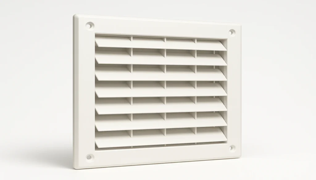
- Rib genişliği (plastik).
- Steel blade thickness must match air slot width; slots narrower than 3 mm leave steel blades that cannot be internally water-cooled and overheat.
- Knit lines in grille ribs retain only 60–80% of base material strength — managing them through gate placement is mandatory.
- Shut-off surfaces require 3–7° draft angle to prevent galling and flash as the mold accumulates wear.
- Beryllium copper inserts in blade areas reduce mold temperature by 15–20°C, cutting cycle time by up to 25%.
What Is the Core Trade-Off in Molded Grille Design?
The core trade-off is that every millimeter gained in air slot width removes exactly one millimeter of mold steel width, reducing the blade’s ability to withstand injection pressure1 and thermal cycling. In our factory, we treat this as a zero-sum equation: a 4 mm air slot requires a 4 mm steel blade, and a blade that narrow needs special alloys or bridge supports to survive 100,000+ production cycles.
“The air slot width and mold steel blade width are equal — one millimeter gained in airflow costs one millimeter of steel.”True
In a molded-in grille, every air slot is formed by a steel blade in the mold that occupies exactly the same space as the slot. A 4 mm air slot requires a 4 mm steel blade. This direct geometric equivalence means every incremental airflow improvement comes at a direct cost to mold structural integrity and thermal management capacity.
“Maximizing open area always improves HVAC grille performance.”False
Open areas above 65% force mold steel blades below 3 mm width, making internal water cooling channels impossible to machine with EDM. Without cooling, blades overheat and the mold fails within 10,000 cycles. The optimal range of 50–65% open area achieves adequate airflow2 while preserving the minimum steel thickness needed for a durable, coolable mold blade.
Aerodynamic engineers typically target 70–80% open area to minimize static pressure drop and fan noise. Tooling engineers counter that grille sections with open area above 65% force steel blades thinner than 3 mm—the threshold below which internal water cooling channels become impossible to machine. Without cooling, the blade heat-soaks during repeated cycles, softening the plastic ribs before ejection and causing 100% part rejection.
| Feature | Molded-In Grille | Separate Metal Guard |
|---|---|---|
| Assembly cost | Zero — integral to housing | Labor + BOM cost for screen + fasteners |
| Tooling complexity | High — EDM shut-offs required | Low — simple housing mold |
| Corrosion resistance | Excellent — plastic does not rust | Moderate — powder coating required |
| Airflow efficiency | Limited by rib min. 2 mm width | Near 90% open area achievable with wire |
| Mold life risk | High if slot width < 3 mm | Not applicable |
The practical resolution is a “Golden Ratio” zone of 50–65% open area, where airflow resistance stays within acceptable limits for most residential and light commercial HVAC products, and the mold steel retains enough mass for reliable thermal management. Departing from this zone in either direction demands engineering justification and typically adds tooling cost.
How Do Key Grille Parameters Affect Mold Longevity?
Five parameters drive both airflow performance and mold life simultaneously. Understanding their interaction allows design teams to negotiate effectively across engineering disciplines rather than defaulting to arbitrary compromises.
| Parameter | Recommended Range | Effect on Mold if Violated |
|---|---|---|
| Open area ratio | 50–65% | Above 65%: blade width drops below 3 mm, preventing internal cooling; mold life under 30,000 cycles. |
| Air slot width | ≥ 3.0 mm | Below 3 mm: EDM cannot produce water channels; blade overheats within 500 shots. |
| Rib width (plastic) | Malzeme seçimi, güvenlik uyumluluğunu da etkiler. Standartlaştırılmış darbe testlerine (IEC 60335'e göre 500 mm yükseklikten 500 g top düşürme) dayanması gereken ızgaralar için kırılgan malzemeler yerine darbe dayanımlı ABS veya PC/ABS karışımları tercih edilir. Darbe testinde başarısız olan ızgaralar genellikle kaburga köklerinde veya dış çerçevenin köşelerinde kırılır — ki bu noktalar, kalıp tasarımımızda maksimum duvar kalınlığı ve minimum birleşme hattı maruziyeti hedeflenen yerlerdir. | Below 2 mm: ribs freeze before packing; short shots in grille center are unavoidable. |
| Steel blade aspect ratio | < 3:1 (H/W) | Above 3:1: blade deflects under 800–1200 bar injection pressure; flash appears in slots. |
| Draft angle (shut-off) | 3°–7° | Below 3°: galling within 5,000 cycles; flash and dimensional drift in slot width. |
Of these, the air slot width is the most critical single constraint, because it simultaneously determines plastic rib strength, steel blade thermal behavior, and achievable open area. In projects where safety standards require narrower slots — for example, IEC 60335 finger-probe compliance sometimes forces slots below 3 mm — we specify beryllium copper inserts as a mandatory tooling upgrade, not an optional enhancement.
Draft angle requirements for shut-off surfaces differ from those for standard pull-direction walls. While 0.5–1° draft suffices for smooth vertical walls, the repeated metal-on-metal contact at a shut-off surface generates friction and micro-galling. Our standard specification is 3° minimum for grille heights up to 15 mm, increasing to 5–7° for tall louvered sections above 25 mm. Deviating from this causes measurable slot width growth after approximately 5,000 cycles.
“Mold flow simulation before cutting steel is mandatory for grille tools to control knit line placement.”True
Gate position determines where polymer flow fronts converge, which directly sets knit line location in grille ribs. Knit lines at rib roots or frame junctions are structurally critical because these are the highest-stress points under fan vibration loading. Only pre-cutting simulation allows repositioning the gate before the costly step of machining the steel, making it a mandatory step in our factory’s grille tooling process.
“A 1° draft angle is adequate for HVAC grille shut-off surfaces if the plastic material has a low friction coefficient.”False
Draft angle requirements for shut-off surfaces are driven by the metal-on-metal contact between core and cavity steel at every mold cycle, not by the plastic material properties. Even with low-friction plastics, the steel-to-steel contact generates galling that progressively widens air slots. Our standard minimum of 3° draft for shut-off surfaces ensures sealing integrity for at least 100,000 cycles regardless of material choice.
What Happens When Grille Steel Overheats During Production?
When grille steel overheats, the sequence of failures follows a predictable pattern: first, the plastic ribs stick to the hot blades; then ejector pins punch through the softened material; finally, the blade fatigues and cracks along its root radius. We documented this exact failure mode on a portable air-conditioner exhaust grille project where 100 mm slots were specified at 4 mm width — technically above the 3 mm threshold, but still too narrow for conventional P20 steel cooling.
During the T1 trial, the grille zone of the tool ran 35°C hotter than the rest of the cavity. Thermocouple measurements at the blade tip reached 78°C above coolant temperature. The result was 100% scrap in the first 200 shots: ribs adhered to the steel, tore on ejection, and left residue that accelerated flash in subsequent cycles.
How Did We Resolve Blade Overheating in Production?
Three interventions resolved the overheating. First, we added perpendicular bridge ribs every 30 mm to break the 100 mm slots into 30 mm segments, reducing unsupported blade length by 70%. This alone stabilized the mold steel sufficiently to eliminate the ejection failure. Second, we replaced the P20 steel in the blade zone with beryllium copper inserts, which reduced peak blade temperature by 18°C. Third, we increased coolant flow rate in the adjacent channels by enlarging the circuit from 8 mm to 12 mm diameter. Cycle time dropped from 60 seconds to 45 seconds, and surface quality improved from a grade-B reject to a grade-A pass.
How Do Knit Lines Form and Why Are They a Structural Risk?
Knit lines form at every grille rib because the plastic flow front splits around each air slot and rejoins on the downstream side. At the point of rejoining, polymer chains from the two flow fronts do not fully entangle — the material temperature has dropped below the critical threshold for molecular diffusion. The result is a planar bond that retains only 60–80% of the base resin’s tensile strength.
For HVAC grilles, this matters more than in most injection-molded parts because the grille is directly exposed to fan vibration. A typical 1,500 RPM axial fan generates continuous vibration at 25 Hz. Over the product lifetime of 10–15 years, this accumulates to 10–15 billion load cycles on every knit line in the grille. Even at stress amplitudes well below the static tensile strength, fatigue crack initiation at the knit line is the dominant failure mode we observe in returned units.
Gate placement controls knit line position, and gate position is therefore a structural engineering decision, not just a process preference. In our factory, we model knit line locations in mold flow simulation before cutting any steel. Our rule: knit lines must not fall at rib roots or at the junction between grille ribs and the outer frame. If simulation shows an unavoidable knit line at a stress-critical location, we add a perpendicular bridge rib to cross-link the flow fronts and force a different convergence geometry.
What Shut-Off Strategies Extend Mold Life in Grille Sections?
The design of the shut-off surface between Core and Cavity determines how quickly the mold begins generating flash in the air slots. A flat parting surface — the simplest geometry — provides only a face seal and begins to leak plastic as soon as wear creates a 0.01–0.03 mm gap. A step or telescoping shut-off provides both a face seal and a lateral shear seal, allowing the mold to tolerate twice the wear before flash becomes unacceptable.
In our standard grille tooling specification, we require step shut-offs on all slots with depth greater than 8 mm. The step height is 0.8–1.2 mm, machined with EDM for surface roughness below Ra 0.4 μm. This surface finish is critical: a rougher surface generates heat from friction during each molding cycle, accelerating the very wear the step geometry is designed to manage.
Steel selection for the shut-off zone also affects mold life significantly. We use H13 tool steel at 48–52 HRC hardness for high-volume grille tools (above 500,000 cycles target), compared to P20 at 30–35 HRC for prototype or lower-volume tooling. H13 provides better wear resistance at the shut-off faces, and its higher chromium content improves corrosion resistance in humid HVAC environments where mold condensation is a persistent issue.

How Do Safety Standards Shape Grille Geometry?
Safety standards UL 507 and IEC 60335-2-80 require that the articulated test finger (an 80 mm jointed probe simulating a human finger) cannot contact the moving fan blade through the grille. This constraint directly limits both slot width and slot depth, and frequently forces louver-style angled geometry that increases mold complexity.
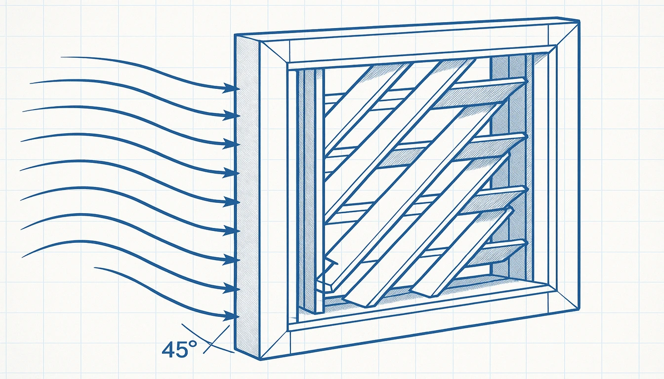
In practice, a straight-through slot of any width wider than 12 mm fails the finger probe test because the probe can enter and reach the fan. Slots narrower than 12 mm pass the test geometrically, but our factory experience shows that slots below 4 mm on linear grilles create unacceptable pressure drop for axial fans in the 150–250 mm diameter range. The solution in most residential HVAC applications is angled louver geometry: slats tilted at 25–45° from vertical allow air flow with low resistance while blocking a straight-line path for the test finger.
Angled louvers require side-action components (slides or lifters) in the mold because the undercut geometry cannot be pulled straight. This adds 15–25% to the tooling cost and introduces additional maintenance points. We recommend purchasing the official test probe hardware before completing the grille geometry — in our factory, we conduct a physical probe test on 3D-printed prototypes before committing any design to steel, catching non-compliant geometries at a cost of hours rather than weeks of tooling rework.
| Factor | Straight Slots | Angled Louvers (30–35°) |
|---|---|---|
| IEC 60335 compliance (slots > 4 mm) | Fails if slot > 12 mm | Passes with correct pitch |
| Pressure drop vs. open area | Lowest at equal open area | 10–15% higher pressure drop |
| Mold complexity | Core/cavity only | Requires slides or lifters |
| Tooling cost premium | Baseline | +15–25% |
| Maintenance points | Lower | Higher — slides need periodic lubrication |
Balancing Safety Compliance with Airflow Performance
The interaction between safety geometry and airflow efficiency is more nuanced than simply choosing narrower slots. Angling the louvers at 30–35° from vertical typically maintains 85–90% of the airflow efficiency of straight-through slots while achieving full IEC 60335 compliance. Louver pitch — the center-to-center spacing between slats — also matters: pitches above 15 mm can allow the probe to enter at an angle and reach the fan even when individual slot width is below 12 mm.
In mini-split indoor units and bathroom exhaust fans, the aesthetic requirement for flush, smooth-looking grilles often drives louver angles above 40°, which increases pressure drop by 10–15% compared to 30° louvers. Our recommendation is to finalize the louver angle in collaboration with the aerodynamic engineer, using computational fluid dynamics or a simple pressure-drop test rig on 3D-printed samples, before the mold design is locked. Post-mold changes to louver angle require slide replacement, costing $2,000–$5,000 per tool depending on size.
How Does Material Choice Affect Safety Compliance?
Material selection influences safety compliance as well. Impact-resistant ABS or PC/ABS blends are preferred over brittle materials for grilles that must withstand the standardized impact tests (500 g ball drop at 500 mm height per IEC 60335). Grilles that fail the impact test typically fracture at rib roots or at the corners of the outer frame — locations that our mold design targets for maximum wall thickness and minimum knit line exposure.
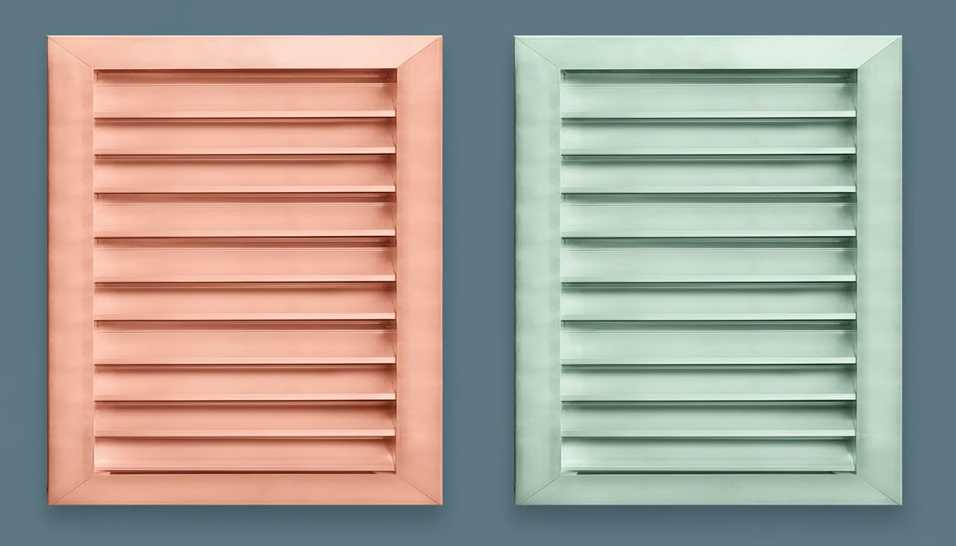
How Do Material Choices Affect Grille Performance Under Vibration?
Material selection for injection-molded grilles involves a three-way trade-off between impact resistance, knit line strength, and mold processability. The most common materials in HVAC grille applications are ABS, PP homopolymer, and ASA, each with distinct performance characteristics at the knit lines that form in every grille rib.
ABS is the industry default for residential HVAC grilles because it combines good impact resistance (notched Izod: 180–350 J/m) with predictable shrinkage of 0.4–0.7%. At knit lines, ABS retains approximately 70–75% of its tensile strength — better than glass-filled materials, worse than unfilled PP. ABS processing temperatures of 220–260°C maintain good melt flow through narrow grille ribs, reducing the risk of short shots in complex geometries.
| Material | Knit Strength | Shrinkage | UV | Best Use |
|---|---|---|---|---|
| ABS | 70–75% | 0.4–0.7% | Poor | Indoor residential |
| ASA | 68–72% | 0.5–0.8% | Excellent | Outdoor/exposed |
| PP | 75–82% | 1.5–2.5% | Moderate | Chemical-resistant fans |
| GF-ABS 30% | 40–50% | 0.3–0.5% | Poor | Low open area (<40%) only |
| PC/ABS | 72–78% | 0.5–0.7% | Moderate | Impact-critical grilles |
How Do Outdoor and Specialty Materials Affect Grille Molding?
ASA (acrylonitrile styrene acrylate) is preferred for outdoor HVAC applications — condensers, fresh-air intakes, and equipment mounted in direct sunlight. Compared to ABS, ASA retains 90% of its impact resistance after 3,000 hours of UV exposure, versus ABS which yellows and embrittles after 500 hours. The trade-off is that ASA is slightly more viscous at equivalent processing temperatures, requiring larger gate diameters and higher injection pressure to fill thin grille ribs completely.
Glass-filled grades (GF-ABS or GF-PP) are tempting for their improved stiffness but present a specific risk at knit lines in grilles. Glass fibers align with the flow direction; at the knit line, fibers from opposing flow fronts meet end-to-end rather than interlocking.
This reduces knit line strength to as low as 40–50% of the base resin, making glass-filled grilles prone to snap failure under impact or vibration fatigue. In our factory, we discourage glass-filled materials in grille sections unless the open area is below 40% and bridge ribs are present to limit unsupported span length.
What Are the Trade-Offs of Polypropylene in Grille Sections?
Polypropylene (PP) offers a lower material cost than ABS and better chemical resistance to cleaning agents — important for bathroom exhaust fans and kitchen range hood grilles. However, PP’s higher shrinkage (1.5–2.5% vs. ABS at 0.4–0.7%) makes warping more likely in asymmetric grille sections. We compensate with tighter cooling circuit balance and longer mold holding times when producing PP grilles, accepting a 15–20% longer cycle time as the cost of dimensional stability.
Frequently Asked Questions?
Konut HVAC ızgaralarında hangi açık alan yüzdesi optimaldir?
For residential HVAC grilles, an open area ratio of 50–65% provides the best balance between airflow performance and mold durability. In this range, air slots are wide enough (typically 3–6 mm) to allow internal water cooling channels in the steel blades, and the blades retain sufficient mass to withstand the thermal and mechanical stresses of injection molding3. Going above 65% reduces steel blade width below 3 mm, making internal cooling impossible with standard EDM tooling and drastically shortening mold life. Going below 50% improves mold durability but increases static pressure drop, raising fan noise and energy consumption in the final HVAC product.
Izgara hava yuvalarında flaşı nasıl önleriz?
Flash prevention in grille air slots requires three parallel strategies. First, use step or telescoping shut-off geometry rather than flat parting surfaces — step shut-offs tolerate twice the mold wear before flash appears. Second, specify H13 steel at 48–52 HRC for the shut-off zone to maximize wear resistance and corrosion resistance. Third, apply crush ribs (raised contact areas of 0.02–0.05 mm height) on the mold steel to ensure tight sealing even as the mold wears over its production life. In our factory, grille molds also receive scheduled shut-off reconditioning every 50,000 cycles to restore surface flatness before flash becomes a production problem rather than a maintenance note.
Cam dolgulu plastikler HVAC ızgaraları için kullanılabilir mi?
Glass-filled plastics can be used for HVAC grilles, but only with specific design accommodations. The primary risk is at knit lines, where glass fiber orientation prevents proper chain entanglement — knit line strength in glass-filled grades drops to 40–50% of base resin strength, versus 65–80% for unfilled materials.
If glass fill is required for stiffness, limit grille open area to below 40%, add perpendicular bridge ribs every 25–30 mm, and conduct fatigue testing at 25 Hz for at least 500 hours. ABS or ASA without glass fill is typically preferred for grille sections.
Izgara kapatma yüzeyleri için hangi pah açısı gereklidir?
Grille shut-off surfaces require substantially more draft than standard injection-molded walls because of the metal-on-metal contact at each molding cycle. Our baseline specification is 3° minimum for shut-off surfaces on grille sections up to 15 mm depth. For deeper grille sections of 15–25 mm, we increase to 5°, and for depths above 25 mm or louver-style angled grilles, we specify 7°. Standard pull-direction walls can use 0.5–1°, but applying that to a shut-off surface causes galling within 5,000 cycles, producing measurable slot width growth and dimensional non-conformance. The additional draft also improves mold release, reducing ejection force on the thin plastic ribs and preventing whitening stress marks.
IEC 60335 parmak probu gereksinimlerine kalıp karmaşıklığı eklemeden nasıl uyum sağlarız?
The simplest path to IEC 60335 compliance without mold slides or lifters is to limit individual air slot width to under 12 mm while ensuring slots are not straight-through. A slight offset between the inner and outer slot opening — 5–8 mm of stagger — blocks the articulated probe path while maintaining adequate airflow.
This geometry can be machined directly into core and cavity without side-action components. We verify compliance on 3D-printed prototypes with the actual test probe before cutting steel, saving weeks of tooling revision.
Izgara deformasyonu neden oluşur ve nasıl düzeltilir?
Grille warping results from differential cooling between thin ribs and the thicker outer frame. Ribs cool and solidify rapidly inside the mold, while the thicker frame continues to shrink after ejection — this differential creates an inward bending moment that produces dish-shaped distortion.
Correction requires balancing wall thickness to within a 2:1 ratio between ribs and frame, placing cooling channels closer to the frame, or using post-mold fixtures that hold the grille flat for 30–60 seconds. PP grilles (shrinkage 1.5–2.5%) are more sensitive to cooling imbalance than ABS (0.4–0.7%).
HVAC ızgara kalıplarında tipik kalıp ömrü nedir?
Mold life for HVAC grille tooling depends on steel grade and maintenance. With P20 steel, a well-maintained grille tool producing ABS parts achieves 300,000–500,000 cycles before shut-off surfaces need reconditioning. H13 steel at 48–52 HRC extends this to 800,000–1,200,000 cycles.
Critical maintenance intervals: shut-off surface cleaning every shift, full polishing every 50,000 cycles, and dimensional inspection of air slot width every 100,000 cycles to catch growth before it exceeds the 0.03 mm flash threshold. Beryllium copper inserts reduce thermal fatigue in blade zones but do not directly affect shut-off wear rates.
-
injection pressure: Injection pressure is the hydraulic or pneumatic force applied to push molten plastic through the runner system and gate into the mold cavity; it is measured in bar or MPa, with typical HVAC plastic parts requiring 600–1200 bar depending on material viscosity and part geometry. ↩
-
airflow: Airflow in HVAC systems refers to the volume of air moved through ducts, grilles, and coils per unit time, typically measured in cubic feet per minute (CFM) or m³/h; it is the primary performance metric for residential ventilation and cooling equipment. ↩
-
injection molding: Injection molding is a manufacturing process in which molten plastic is injected under pressure into a precision-machined steel mold cavity, cooled, and ejected as a finished part; it is the dominant production method for HVAC plastic components including grilles, housings, drain pans, and duct connectors. ↩