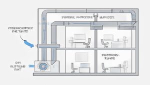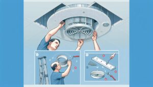
In my years managing HVAC OEM production lines, few things have caused more "field failure" reports than the humble condensate trap. It is a deceptively simple plastic component—often costing less than a dollar—that, if designed or installed incorrectly, can cause thousands of dollars in water damage or shut down a high-static Air Handling Unit (AHU).
I have seen perfectly molded condensate pans overflow not because of a leak in the pan, but because the trap geometry couldn’t overcome the negative static pressure of the blower. The fan essentially "sucks" the water back up the drain line, a phenomenon we call "geysering" or "hold-up."
This guide breaks down the physics and manufacturing realities of HVAC condensate traps, specifically comparing the standard P-Trap against the Running Trap (often called the R-Trap), and how to select the right condensate drain design for your system.
– Traps are not just plumbing; they are pressure seals. Their depth must exceed the internal static pressure of the HVAC unit.
– P-Traps are the gold standard for negative pressure (draw-through) systems due to their deep water seal capability.
– R-Traps (Running Traps) are compact and suitable for positive pressure or tight spaces but fail easily under high negative static pressure.
– Material selection (PVC vs. ABS) impacts solvent welding compatibility during installation.
What Are P-Traps and R-Traps in HVAC?
Before discussing manufacturing, we must define the geometry.
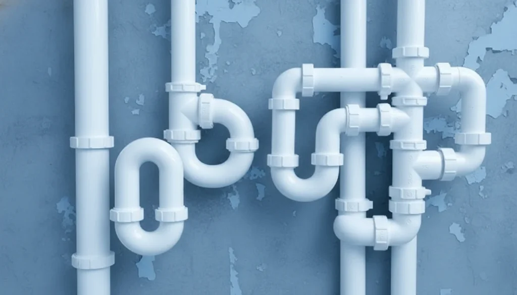
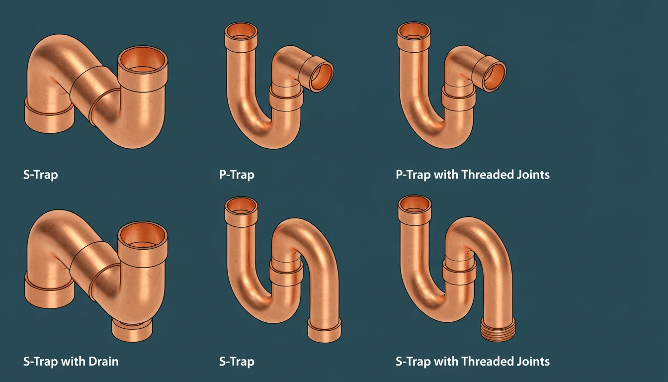
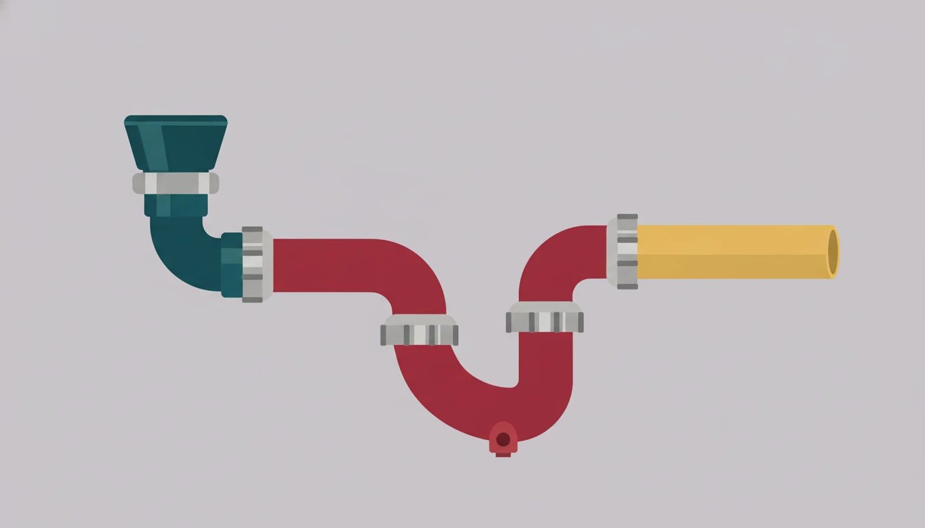
- P-Trap: The standard "loop" shape found under sinks, but with specific depth requirements for HVAC. It creates a vertical water column that acts as a barrier against air movement.
- R-Trap (Running Trap): A more elongated, shallower dip in the line. It looks like a "U" stretched out horizontally. It is often used where vertical clearance (height) is very limited.

Key Parameters: Geometry vs. Physics
The effectiveness of a trap is determined by the "Water Seal Depth." In the factory, we test these traps against variable frequency drives (VFDs) to see at what static pressure the seal breaks.
| Parameter | P-Trap (Standard) | R-Trap (Running/Shallow) | Importance |
|---|---|---|---|
| Geometry | Tight vertical loop | Elongated horizontal dip | Affects the water column height (Hydrostatic Head). |
| Seal Depth | Typically 2" to 4" | Typically 1" to 2" | Must be greater than the unit’s negative static pressure wenn die Falle verstopft oder trocken ist, ohne das Rohr zu durchtrennen. |
| Space Required | High vertical clearance | High horizontal clearance | P-Traps need height; R-Traps need length. |
| Primary Use | Negative Pressure (Draw-Through) | Positive Pressure (Blow-Through) | Negative pressure tries to pull water back; Positive pressure pushes it out. |
| Material | Schedule 40 PVC / ABS | Schedule 40 PVC / ABS | Standard plumbing dimensions apply. |
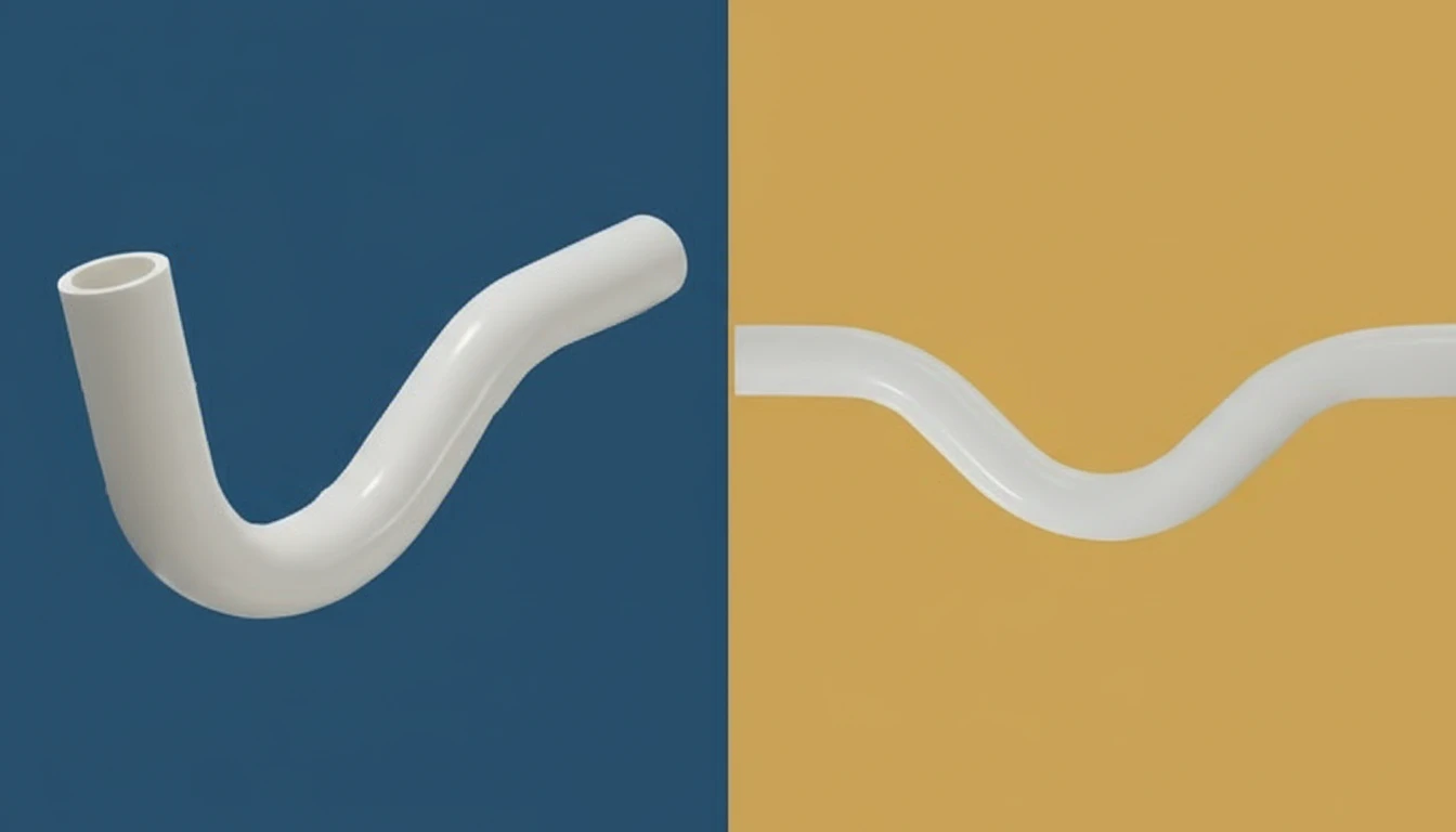
Myth vs. Fact: Trap Design
The shape dictates the water column height. If the trap is too shallow (like many R-Traps), a high-static fan will suck the water out of the trap, breaking the seal and allowing air to rush in.
In a draw-through system (fan after the coil), the negative pressure prevents gravity drainage unless a P-Trap creates a water column heavy enough to overcome the suction.
The Physics of Negative Pressure Drainage
This is the technical core that many designers overlook.
Most commercial AHUs are Draw-Through. The fan pulls air through the cooling coil. This creates a vacuum (negative pressure) inside the drain pan area.
- If the fan generates -2.0 inches of static pressure, and your trap only holds 1.0 inch of water, the air suction wins.
- Air rushes in through the drain pipe.
- This rushing air acts like a dam, holding the water in the pan.
- Result: The pan overflows inside the unit, causing leaks, mold, and rusted chassis components.
In this scenario, a deep P-Trap is mandatory. An R-Trap rarely provides enough vertical depth to counter the suction.
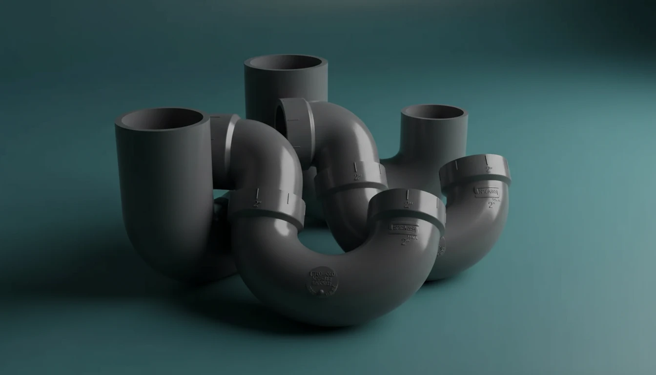
Manufacturing and Material Considerations
When we manufacture plastic trap components or kits, we focus on three things:
1. Material Selection (PVC vs. ABS)
- Polyvinyl Chloride (PVC): The industry standard for commercial HVAC. It is rigid, chemical resistant, and cheap. However, in our molding facilities, PVC is corrosive to molds (releases hydrochloric acid gas), requiring stainless steel tooling.
- Acrylonitrile Butadiene Styrene (ABS): Common in residential. It is easier to mold but has lower chemical resistance.
- Factory Tip: We often mold clear PVC traps now. Why? So maintenance teams can see if the trap is clogged or dry without cutting the pipe.
Sicherheitsüberlaufschalteranschlüsse?
- Fittings (Elbows/U-bends): These are injection molded. The challenge is ensuring the inner surface is perfectly smooth. Any flash (excess plastic) on the inside creates turbulence and catches algae/gunk, leading to clogs.
- Pipe: Extruded.
- Pre-formed Traps: We now injection mold "uni-body" P-traps that eliminate leak points (joints). These are superior to assembling a trap from elbows and pipe.
Advantages and Disadvantages
| Type | Advantages | Polycarbonat (PC) |
|---|---|---|
| P-Trap | • Creates deep seal for high static pressure. • Prevents suck-back/geysering. • Standard industry practice. |
• Requires significant vertical height under the unit. • Can dry out if not used for months (requires priming). |
| R-Trap | • Low profile (fits in tight ceilings). • Good for positive pressure (blow-through) units. • Easier to clean out (often). |
• Shallow seal fails under negative pressure. • Prone to air-locking. • Taking up horizontal space can be awkward. |
Practical Tips for HVAC Trap Installation
From the perspective of minimizing warranty claims on our equipment, here are the rules we enforce:
- The "2-Inch Rule": For a negative pressure system, the outlet of the trap must be lower than the inlet by at least the system’s static pressure (in inches) plus 1 inch. This safety factor accounts for filter loading (which increases static pressure over time).
- Cleanouts are Mandatory: Algae grows in stagnant water. We design our pre-molded traps with a screw-cap cleanout on the top or the bend. If you glue a trap solid without a cleanout, you are building a future maintenance nightmare.
- Insulation: In humid environments (like Florida or SE Asia manufacturing hubs), the cold water in the trap will cause the outside of the plastic pipe to sweat. We recommend using pre-insulated traps or wrapping them with foam tape to prevent ceiling damage below.
Common HVAC Application Scenarios
- Rooftop Units (RTUs): Usually require deep P-Traps because they run high static pressure to push air down duct shafts.
- Fan Coil Units (FCUs): Often have limited ceiling space. If positive pressure (fan blows over coil), an R-Trap or simple elbow might suffice. If negative, you must find space for a P-Trap or use a waterless trap (ball-valve type).
- Furnace/Split Systems: Usually lower static pressure, but P-Traps are still best practice to prevent sewer gas (if tied to plumbing) or bugs from entering the system.
Stepwise Manufacturing/Selection Recommendations
- Calculate Static Pressure: Do not guess. Read the fan curve. If the unit pulls -1.5" w.g., your trap needs a >3" total drop.
- Select Geometry:
- Negative Pressure -> P-Trap (Non-negotiable).
- Positive Pressure -> P-Trap or R-Trap.
- Choose Features:
- Transparent material (Clear PVC) for inspection?
- Integrated cleanout caps?
- Safety overflow switch ports?
- HVAC-Wartungstipps: Wesentliche Erkenntnisse für Langlebigkeit Prime with water immediately. Verify no air is rushing into the pipe while the unit is running.
Frequently Asked Questions (FAQ)
1. Why is water spraying off my cooling coil?
This is often "blow-off," but it can be caused by a trap that is too shallow. If the trap seal breaks, air rushing in at high velocity can hit the water in the pan and spray it back into the airstream.
2. Can I use an R-Trap on a negative pressure system?
Generally, no. Most R-Traps do not provide enough vertical water column depth to overcome the suction of a standard commercial blower. You risk the pan overflowing.
3. What is a "waterless" trap?
A waterless trap uses a mechanical seal (like a silicone diaphragm or a floating ball) instead of standing water. We recommend these for units that sit idle for long periods (like vacation homes) where a standard water seal would evaporate.
4. Why does my drain line gurgle?
Gurgling usually indicates the trap is partially dry or the seal is barely holding against the air pressure. It’s a warning sign that the trap geometry is borderline insufficient for the fan’s power.
5. Should I cap the vent pipe?
The vent pipe after the trap should remain open to allow water to flow freely (breaking the siphon effect). However, it should be high enough that water doesn’t overflow from it if the drain line backs up.
Technical Summary
In the debate of P-Trap vs R-Trap, physics dictates the winner. For the vast majority of commercial and residential systems utilizing negative pressure (draw-through) coils, the P-Trap is the only reliable solution due to its ability to maintain a deep water seal against air suction. The R-Trap has its place in low-profile, positive-pressure applications, but using it incorrectly is a primary cause of condensate leakage. For HVAC manufacturers and installers, prioritizing correct trap depth calculations over space-saving shortcuts is the only way to ensure long-term, leak-free performance.