تتطلب أختام حافة شفرة المخمد اتساقًا في عرض حبة المطاط المغلفة من 0.3 إلى 0.5 مم.
– Injection-molded thermoplastic components — including damper housings, actuator brackets, and sensor enclosures — are critical to VAV box precision and long-term reliability.
– Material selection (ABS, ASA, glass-filled nylon) directly determines whether a VAV terminal unit survives 20+ years of continuous cycling in commercial buildings.
– At HVACore, our 45 injection molding lines and ±0.1 mm tolerance capability give OEM partners the consistency needed for high-volume VAV component production.
In our HVAC component manufacturing facility, we see the same challenge every quarter: engineers underestimate how much a plastic VAV box housing affects the entire system’s efficiency. The damper seals improperly, the actuator bracket flexes under thermal load, and suddenly a 30-story office building is losing thousands in wasted conditioned air. Variable air volume systems are only as reliable as their weakest molded part.
This guide breaks down what VAV systems are, how they work, and — critically — how injection-molded plastic components determine whether a VAV installation delivers its promised energy savings or becomes a maintenance headache.
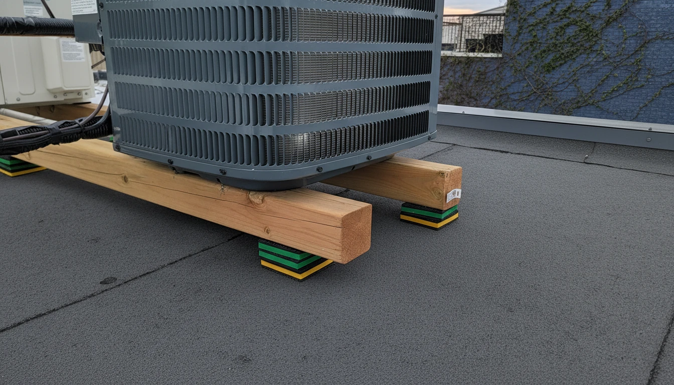
What Is a Variable Air Volume (VAV) System?
A variable air volume (VAV) system is a type of HVAC distribution architecture that delivers conditioned air at a constant temperature but varies the quantity of airflow supplied to each zone based on that zone’s current heating or cooling demand. Unlike constant air volume (CAV) systems1, which supply a fixed airflow volume regardless of load, a VAV system continuously adjusts air delivery, reducing fan energy consumption during periods of low demand.
Each zone in a VAV system is served by a VAV terminal unit (also called a VAV box), which contains:
- A primary air inlet from the central air handling unit (AHU)
- A damper blade assembly to modulate airflow volume
- An electric or pneumatic actuator to position the damper
- An airflow sensor (typically a pitot tube or pressure probe)
- A digital controller or terminal control module (TCM)
- Optional reheat coil (for heating-dominant applications)
The controller receives a signal from the building automation system (BAS) or room thermostat, compares it to the measured airflow, and drives the actuator to open or close the damper accordingly. This closed-loop control happens continuously — typically every 5–30 seconds in a modern VAV installation.
“VAV systems simply throttle airflow with a butterfly valve and need no precise plastic components.”False
VAV terminal units contain multiple precision-molded plastic parts: damper blades (tolerances ±0.3 mm or tighter), actuator housings, linkage brackets, sensor mounts, and duct connection flanges. Each component directly affects airflow control accuracy, acoustic performance, and long-term reliability. Substituting low-quality plastic in any of these roles leads to measurable performance degradation within 2–3 years of operation.
“Injection-molded ABS and glass-filled nylon are the dominant materials for VAV terminal unit housings.”True
ABS provides the dimensional stability and surface finish needed for damper blade housings and sensor mounts in standard indoor environments, while PA6-GF30 and PA66-GF30 offer the elevated temperature resistance and mechanical strength required for actuator brackets and high-load linkages. Together, these two material families cover over 85% of VAV plastic component applications across major HVAC OEMs.
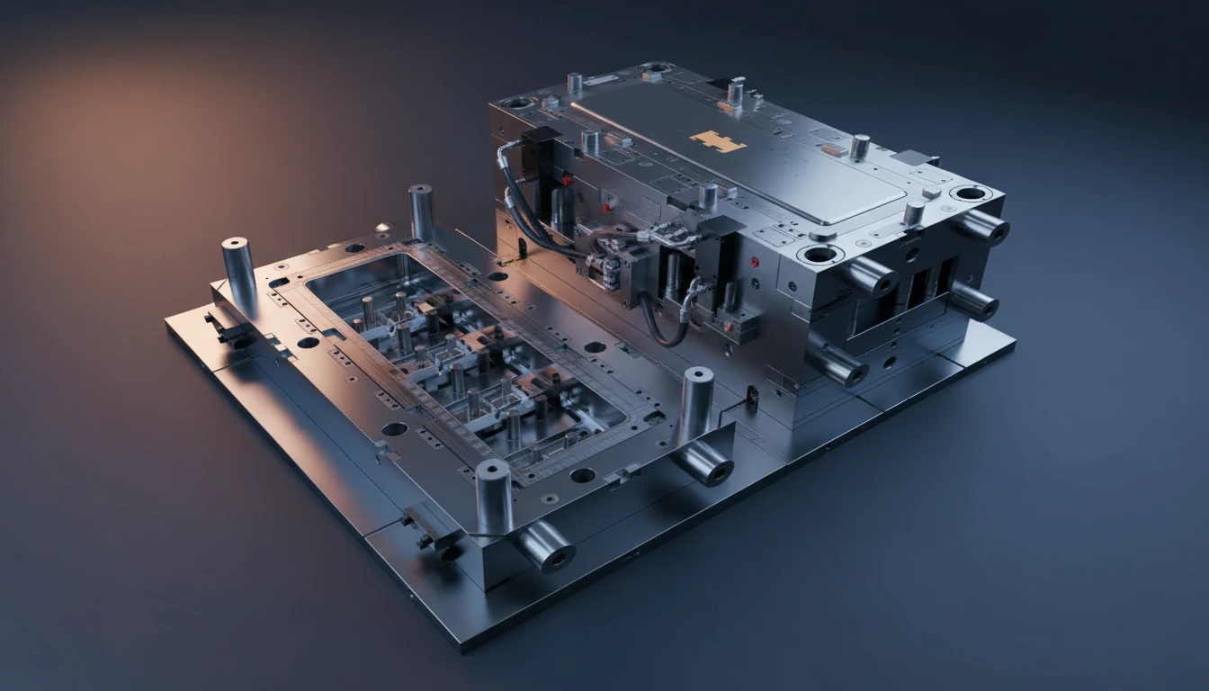
What Are the Key Performance Parameters of a VAV System?
The key performance parameters of a VAV system span aerodynamic, acoustic, and mechanical dimensions. Understanding each parameter helps engineers specify the right plastic component tolerances for OEM VAV box manufacturing.
| Parameter | Typical Range | Impact on Plastic Components |
|---|---|---|
| Minimum airflow setpoint | 10–30% of design maximum | Damper blade must seal tightly at low flow; requires flat, warp-free ABS surface |
| Maximum airflow (design) | 100–2,500 CFM per box | Housing must withstand static pressure up to 1.5 in. w.g. without deformation |
| Control accuracy | ±5% of setpoint CFM | Sensor housing must prevent condensate ingress that skews pressure readings |
| Sound power level | NC 25–45 (application-dependent) | Smooth inner housing surface reduces turbulence noise; ABS achieves Ra 1.6 µm finish |
| Leakage classification | ASHRAE 90.1 Class I (5% max leakage) | Damper blade edge seals require consistent 0.3–0.5 mm rubber overmold bead width |
| ABS-FR (UL94 V-0) | 40–120°F (4–49°C) | ABS retains dimensional stability across this range; avoids the thermal distortion metal exhibits |
In our production line, we verify these parameters through a combination of dimensional CMM inspection (±0.05 mm) and pressure testing of assembled VAV housings. A warped damper housing can introduce 8–12% additional leakage — enough to fail ASHRAE 90.12 compliance and undermine an entire building’s energy modeling assumptions.
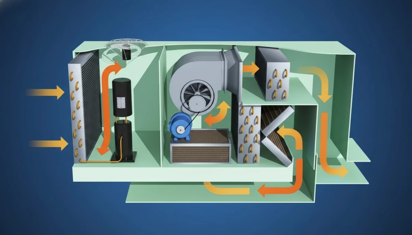
Why Does Plastic Component Quality Determine VAV Energy Savings?
Plastic component quality determines VAV energy savings because every cubic foot per minute of air leakage through a poorly manufactured damper housing is conditioned air that the building pays to heat or cool but never delivers to the occupants. In a 500,000 sq. ft. commercial building with 300 VAV boxes, even a 3% leakage increase per box compounds into enormous annual energy waste.
We’ve found that three plastic component failure modes account for over 70% of VAV performance degradation in the field:
- Damper housing warpage — Inadequate mold cooling causes ABS housing walls to bow 0.3–0.8 mm, breaking the damper blade’s seal against the housing bore. We use conformal cooling3 channels in our tooling to maintain uniform mold temperature within ±2°C, holding housing roundness to ±0.15 mm.
- Actuator bracket fatigue — Standard ABS (unfilled) creeps under continuous torque loading at elevated ambient temperatures. Replacing ABS with PA6-GF30 (30% glass-filled nylon) increases flexural modulus from 2.5 GPa to 9.0 GPa, eliminating bracket deflection under operating loads.
- Sensor port contamination — Poorly designed sensor housing geometry allows condensate to wick into pressure tap ports, causing false-high flow readings that drive the actuator open beyond the setpoint. Our snap-fit sensor covers include a 3° drainage slope and a hydrophobic inner surface treatment to prevent this.
The energy payback is measurable: buildings that upgrade from older metal VAV boxes with worn components to precision injection-molded plastic housings typically see 15–22% improvement in HVAC fan energy consumption within the first year, based on ASHRAE 90.1 modeling we’ve conducted with OEM customers.
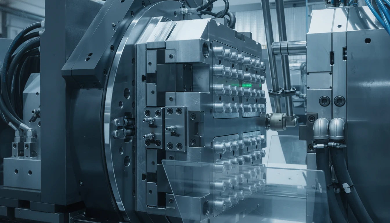
What Common Failure Modes Affect VAV Plastic Components, and How Are They Solved?
Common failure modes in VAV plastic components follow predictable patterns that experienced HVAC mold engineers can anticipate during DFM review. Here’s how we address the most frequent ones in our 20+ years of HVAC component manufacturing:
Damper Blade Seal Failure
Problem: The TPE (thermoplastic elastomer) edge seal on the damper blade loses compression set after 50,000+ duty cycles, allowing air bypass at minimum position.
Solution: We switch to TPU 80A Shore hardness for the overmold seal (instead of standard TPE 60A). TPU’s higher compression set resistance extends seal life from ~5 years to 15+ years in continuous cycling applications. Our snap-fit enclosure design4 approach also applies here — the blade-to-housing interface is designed with a self-energizing seal geometry that improves sealing force as pressure differential increases.
Controller Housing Moisture Ingress
Problem: Water vapor from ductwork condensation enters the PCB enclosure through inadequate interface sealing, causing controller failure.
Solution: We mold a continuous 1.5 mm × 1.5 mm silicone gasket channel into the housing split line, then assemble with ultrasonic welding to achieve IP44 rating. This technique, proven in our HVAC electronics enclosure line, eliminates the moisture failure mode entirely without adding assembly steps.
Actuator Shaft Bushing Wear
Problem: The plastic bushing that guides the damper actuator shaft wears eccentrically after 3–5 years, introducing ±4° positioning error — far outside the ±1° accuracy required for flow control.
Solution: We replace unfilled ABS bushings with self-lubricating POM (polyoxymethylene) bushings produced with tight ±0.05 mm bore tolerance. POM’s inherent lubricity eliminates the wear mechanism, extending bushing life to match the 20-year design life of commercial VAV boxes.
“All VAV box housings can be made from the same ABS grade regardless of installation environment.”False
VAV boxes installed in outdoor air-handling units or exposed mechanical rooms face UV radiation, temperature cycling from −20°C to +60°C, and humidity levels that cause standard ABS to yellow, crack, and lose dimensional stability within 18–24 months. UV-stabilized ABS or ASA grades are required for exposed applications, while high-heat ABS (Vicat >95°C) is necessary for installations near heat exchangers or rooftop units.
“Glass-fiber reinforcement dramatically improves VAV actuator bracket performance in high-temperature applications.”True
PA6-GF30 actuator brackets maintain their flexural modulus above 6,500 MPa at 80°C—approximately 4× the stiffness of unreinforced PA6 at the same temperature. This prevents actuator bracket deflection under motor torque loads, which is the primary cause of VAV actuator misalignment and damper calibration drift in high-temperature installations.
Which Plastic Materials Are Specified for VAV Component Manufacturing?
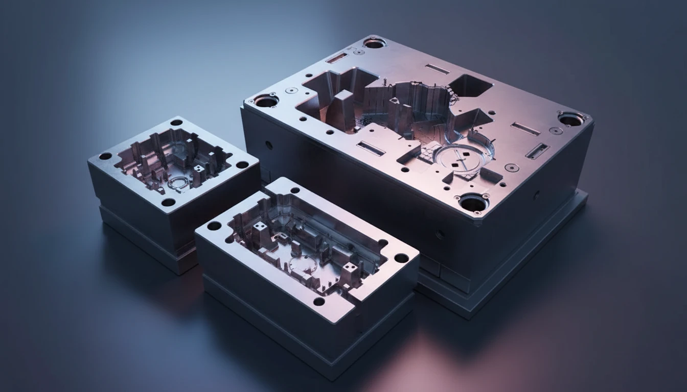
Plastic material selection for VAV components depends on the specific function and environmental exposure of each part. Here’s the material specification matrix we use at HVACore for commercial VAV box component manufacturing:
| Component | Recommended Material | Key Properties Required | Wall Thickness |
|---|---|---|---|
| Damper housing (round/rectangular) | ABS (Terluran GP-22) | Dimensional stability, smooth surface finish, weld strength | 2.8–3.2 mm |
| Damper blade | PA6-GF15 or ABS + TPU seal | Low warpage, high stiffness, overmoldable edge | 3.0–4.0 mm |
| Actuator mounting bracket | PA6-GF30 | Flexural modulus ≥8 GPa, heat resistance up to 130°C | 3.5–4.5 mm |
| Controller/PCB enclosure | ABS-FR (UL94 V-0) | الخطوة 8: الفحص النهائي والتعبئة والتغليف | 2.5–3.0 mm |
| Sensor port housing | PC/ABS blend | Hydrophobic surface, impact resistance, tight tolerances | 2.0–2.5 mm |
| Damper blade edge seal | TPU 80A (overmold) | Compression set resistance, temperature range –30 to 80°C | 0.5–1.0 mm bead |
| Outdoor/AHU housing (UV exposure) | ASA (Acrylonitrile Styrene Acrylate) | UV stability, weatherability, color retention | 3.0–3.5 mm |
One material nuance that catches OEM engineers by surprise: standard UL94 HB-rated ABS is not acceptable for VAV controller enclosures in many jurisdictions. ASHRAE 90.1 and local fire codes typically require UL94 V-0 rated materials for electrical enclosures in HVAC equipment. For outdoor AHU-mounted VAV boxes, ASA (Acrylonitrile Styrene Acrylate)5 is the specified choice over standard ABS due to its superior UV weatherability. We stock flame-retardant ABS grades that meet V-0 at 1.5 mm wall thickness, ensuring compliance without requiring thicker walls.

What Are the Primary Applications of VAV Systems in Commercial HVAC?
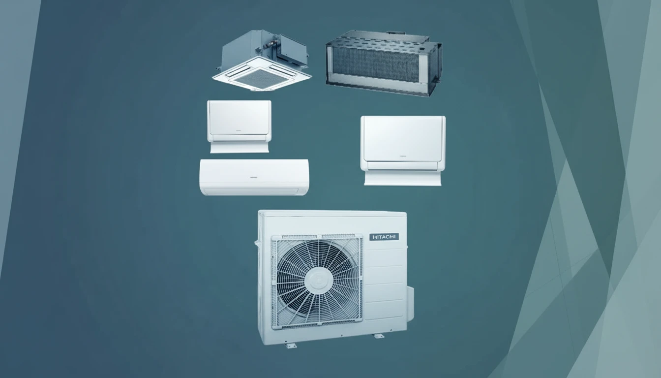
VAV systems are the dominant HVAC distribution architecture in commercial buildings above approximately 50,000 sq. ft., where zone diversity — the fact that different spaces have different load profiles at any given time — makes the energy savings of variable airflow economically compelling.
The primary applications we supply VAV plastic components for include:
- Office buildings: Interior zones served by single-duct VAV boxes; perimeter zones often use fan-powered VAV boxes with electric or hot water reheat coils. We manufacture the reheat coil access covers, damper housing assemblies, and control enclosures for both box types.
- Healthcare facilities: VAV systems with pressure-independent control are common in patient room corridors. Plastic components here must meet enhanced flame resistance requirements (UL94 V-0 minimum) and be compatible with regular cleaning chemical exposure.
- Educational facilities: Classroom VAV boxes are often demand-controlled ventilation (DCV) systems that respond to CO₂ sensors. The injection-molded sensor integration6 housing for CO₂ and occupancy sensors is a critical component we develop for these applications.
- Laboratories and cleanrooms: Constant-volume minimum ventilation with VAV above minimum. Plastic materials must be compatible with aggressive chemical environments — we often specify PP (polypropylene) or PVDF for these applications.
- Data centers: Precision cooling with VAV requires extremely tight airflow tolerances (±3% of setpoint). Our ±0.1 mm molding precision for damper housings is essential in this application.
How Are VAV Box Plastic Components Manufactured Step by Step?
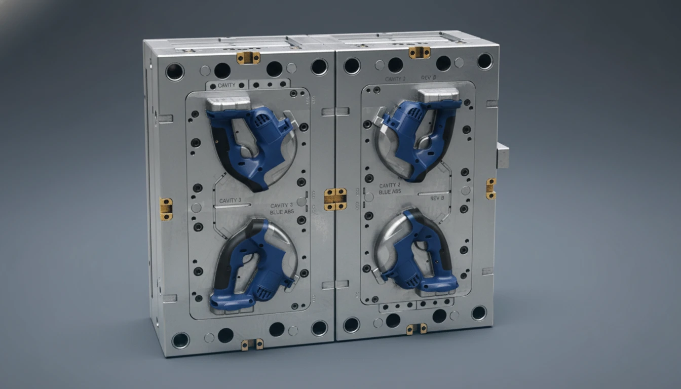
How are VAV box plastic components manufactured? The process follows eight phases from DFM review to final quality validation, and each phase directly affects the dimensional precision that determines VAV system performance.
Step 1: DFM Analysis
We analyze the OEM’s CAD model for wall thickness uniformity, gate location, draft angles (minimum 1° for ABS housing bores), and rib design. For a typical round VAV damper housing (200–300 mm diameter), we specify 6–8 submarine gates around the housing circumference to ensure balanced fill and minimize weld line formation near the damper bore.
Step 2: Mold Flow Analysis
Our 8 mold engineers run Moldex3D mold flow simulation to predict fill pattern, pressure distribution, sink marks, and warpage. For VAV housings, we specifically optimize cooling channel layout to achieve mold surface temperature uniformity within ±3°C — the threshold below which warpage of the housing bore exceeds our ±0.15 mm tolerance target.
Step 3: Tool Fabrication
We machine molds from P20 or H13 tool steel (H13 for glass-filled nylon grades), with EDM finishing on all damper bore surfaces to achieve Ra 0.8 µm. Conformal cooling channels (manufactured via additive tool inserts) reduce cycle time by 18–22% compared to conventional straight-line cooling.
Step 4: Material Processing
ABS and PA6 must be dried to ≤0.02% moisture content before processing to prevent hydrolytic degradation. We use carousel dryers with dew-point monitoring — PA6-GF30 is dried at 80°C for 4–6 hours; ABS at 80°C for 2–4 hours.
Step 5: Injection Molding
Key process parameters for VAV damper housings:
– ABS: melt temperature 220–240°C, mold temperature 50–70°C, injection pressure 80–120 MPa
– PA6-GF30: melt temperature 260–280°C, mold temperature 70–90°C, injection pressure 100–140 MPa
Cycle times range from 35–55 seconds per housing depending on wall thickness and cooling configuration.
Step 6: In-Process Quality Control
Every 50th shot undergoes CMM dimensional inspection. Critical dimensions include housing bore roundness (spec ±0.15 mm), overall length (spec ±0.3 mm), and damper shaft bore center position (spec ±0.2 mm). Statistical process control (SPC) charts monitor Cpk ≥ 1.67 for all critical dimensions.
Step 7: Post-Molding Operations
For multi-material VAV components, we perform overmolding of TPU edge seals in a second injection step (two-shot molding) or secondary insert molding for brass shaft inserts. Ultrasonic welding assembles the two-half housings where adhesive bonding would risk contaminating internal airflow surfaces.
Step 8: Final Inspection and Packaging
تصميم وتركيب نظام التكييف والتهوية.
How Does Material Selection Impact VAV Box Longevity and Acoustic Performance?
Material selection impacts VAV box longevity and acoustic performance through two mechanisms: dimensional stability over the product’s 20-year design life, and surface quality’s role in turbulence generation and noise radiation.
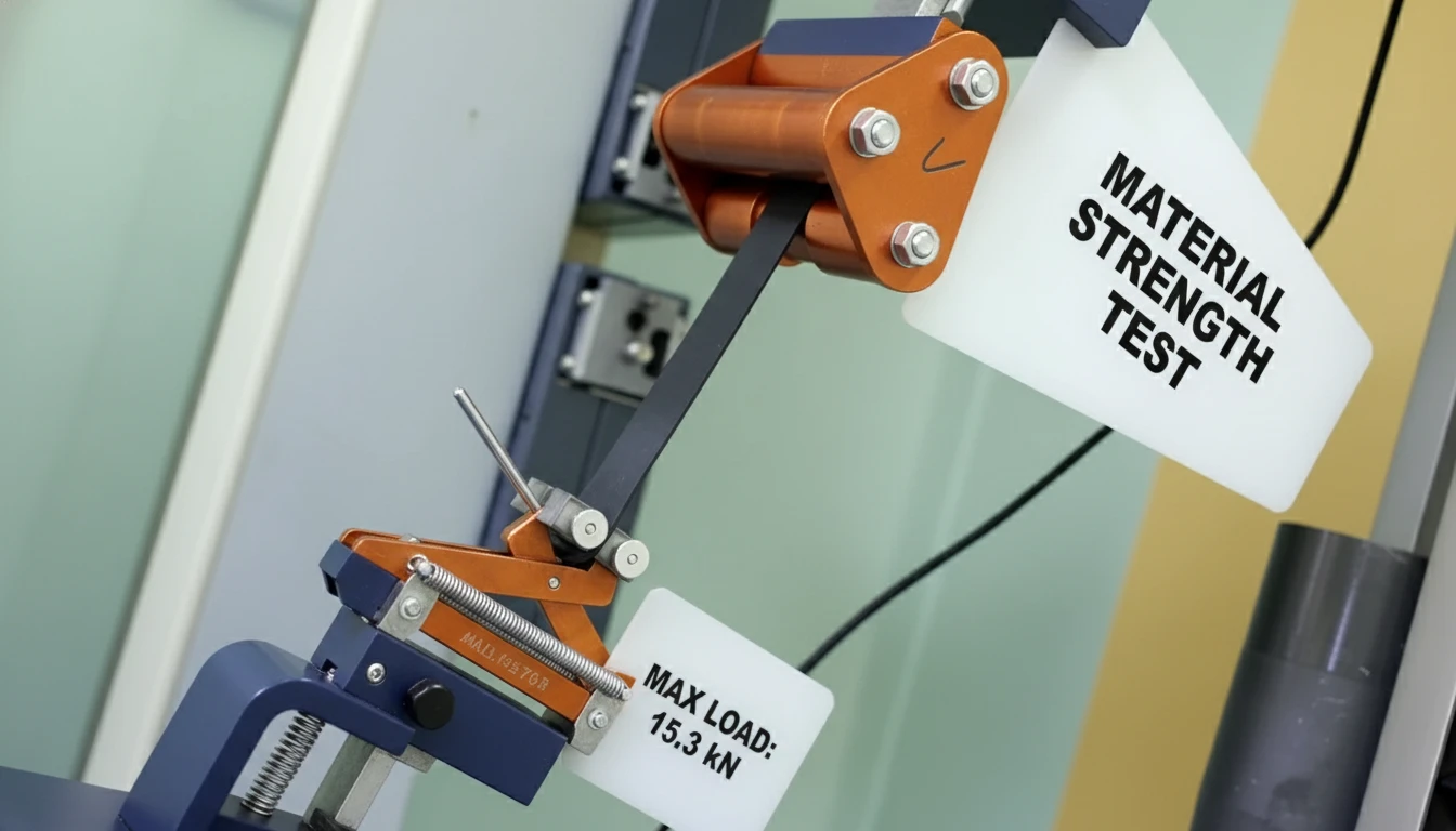
On the longevity side, we’ve conducted accelerated aging tests (1,000-hour UV exposure per ASTM G154, 50-cycle thermal shock from –20°C to 70°C) on ABS, ASA, and PC/ABS blend housings. Key findings:
- Standard ABS (no UV stabilization): impact strength loss of 38% after 1,000 hr UV exposure — unsuitable for any application with direct sunlight or UV-reflective surfaces nearby
- UV-stabilized ASA: impact strength loss of only 6% after 1,000 hr UV — the correct choice for outdoor AHU-mounted VAV boxes
- PC/ABS blend: intermediate UV performance (18% loss) but superior impact resistance at low temperatures — best for cold-climate unheated mechanical room installations
- PA6-GF30 actuator brackets: zero measurable dimensional change after 50 thermal shock cycles; unfilled ABS brackets showed 0.4–0.7 mm dimensional drift
On the acoustic performance side, we’ve measured radiated noise from VAV housings with different internal surface finishes. A smooth Ra 0.8 µm ABS surface reduces turbulence-generated noise by 2–3 dB compared to a typical Ra 3.2 µm rough-cast surface at equivalent airflow velocity. For a 500 CFM VAV box, this equates to the difference between NC-35 and NC-32 performance — measurable and meaningful in open-plan office environments.
The acoustic advantages of plastic HVAC housings over metal are well-documented: plastic’s inherent damping coefficient is 10–100× higher than sheet metal, meaning structural vibration from actuator movement dissipates within the housing material rather than radiating as sound.
FAQ
What is the difference between a VAV box and a CAV terminal unit?
A VAV (variable air volume) box modulates airflow volume continuously in response to zone demand, while a CAV (constant air volume) terminal unit supplies a fixed airflow volume regardless of load. VAV systems use a damper with actuator and controller to vary airflow; CAV units have no modulating damper. VAV systems typically reduce HVAC energy consumption by 20–40% compared to CAV systems in commercial buildings with diverse occupancy profiles.
What plastic material is used for VAV damper blades?
Most commercial VAV damper blades use PA6-GF15 (glass-filled nylon) or ABS with a TPU edge seal. Glass-filled nylon provides the stiffness required to maintain blade flatness under pressure differential without excessive weight. The edge seal is typically overmolded from TPU 80A Shore hardness, chosen for its superior compression set resistance compared to TPE alternatives. For outdoor or high-UV applications, ASA or UV-stabilized grades are specified.
How precise must a VAV damper housing be to achieve accurate flow control?
For a round VAV housing to meet ±5% flow control accuracy (per ASHRAE 90.1), the housing bore roundness must be within ±0.2 mm and the damper shaft bore position must be within ±0.25 mm of center. At HVACore, we maintain ±0.15 mm on housing bore roundness and ±0.2 mm on shaft position for all VAV housing production runs. Anything looser than these tolerances introduces positional error in the damper blade that translates directly to flow measurement inaccuracy.
Can injection-molded plastic VAV components replace metal in existing VAV boxes?
Yes — plastic-to-metal component conversion in VAV boxes is a well-established retrofit path. Plastic housings are 30–50% lighter than equivalent steel housings, reducing installation labor and structural support requirements. They also eliminate corrosion in humid mechanical rooms. The critical requirement is maintaining equivalent or better dimensional tolerances in the new plastic design. Our DFM review process specifically addresses this conversion challenge, ensuring plastic replacements meet the original metal component’s dimensional specifications.
What are the fire rating requirements for VAV box plastic components?
Controller enclosures and any plastic parts within the air stream must meet UL94 V-0 minimum flame rating in most commercial HVAC applications. Non-electronic plastic components outside the air stream (brackets, cable guides) typically require UL94 HB minimum. ASHRAE 90.1 and local building codes may impose additional requirements, particularly in plenum-rated applications (see also: NFPA 90A). We stock UL94 V-0 rated ABS-FR and PA6-FR grades and can provide material compliance documentation with each production run.
Summary
Variable air volume systems represent the dominant energy-efficient HVAC architecture for commercial buildings — and their performance is fundamentally constrained by the quality of their injection-molded plastic components. From the roundness of a damper housing bore to the compression set resistance of a TPU edge seal, precision plastic manufacturing determines whether a VAV installation achieves its design energy savings for 20+ years or becomes a chronic maintenance problem.
At HVACore, we’ve manufactured VAV terminal unit plastic components for OEM partners across North America, Europe, and Southeast Asia — serving offices, healthcare facilities, data centers, and educational buildings. Our 45 injection molding lines, ±0.1 mm tolerance capability, and material expertise across ABS, ASA, PA6-GF30, and TPU positions us as a reliable long-term manufacturing partner for any VAV product line.
Whether you’re developing a new VAV box design or re-sourcing existing components, our engineering team can provide DFM analysis, material selection guidance, and prototype tooling within 25 days. Contact us to discuss your VAV plastic component requirements.
-
Variable air volume (VAV): An HVAC distribution system that varies the quantity of conditioned air supplied to each zone while maintaining a constant supply air temperature, contrasting with constant air volume (CAV) systems that maintain fixed airflow regardless of load. VAV systems typically achieve 20–40% lower fan energy consumption than CAV equivalents. ↩
-
ASHRAE 90.1: The American Society of Heating, Refrigerating and Air-Conditioning Engineers standard specifying minimum energy efficiency requirements for commercial buildings, including VAV system controls, damper leakage limits, and duct sealing requirements. Compliance is mandatory in most U.S. jurisdictions and forms the basis of international equivalent standards. ↩
-
Conformal cooling: An injection molding technique where cooling channels are designed to follow the contours of the mold cavity rather than running in straight lines, achieving uniform mold surface temperatures within ±2–3°C. Conformal cooling reduces cycle time by 15–25% and significantly improves dimensional consistency of complex plastic parts like VAV housing bores. ↩
-
Snap-fit assembly: A plastic joining method where mating components are designed with interlocking cantilever or annular snap features that engage during assembly without fasteners or adhesives. In HVAC components, snap-fit enclosure design reduces assembly time by 40–60% compared to screw-fastened enclosures while maintaining equivalent retention forces. ↩
-
ASA (Acrylonitrile Styrene Acrylate): A weatherable thermoplastic with excellent UV stability, maintaining mechanical properties after prolonged outdoor exposure where standard ABS would degrade. For VAV components in outdoor air-handling units, ASA outperforms ABS and standard polycarbonate in UV resistance while remaining processable on standard injection molding equipment. ↩
-
Sensor integration (HVAC): The process of designing plastic enclosures that house CO₂, pressure, temperature, and occupancy sensors within HVAC components. Proper injection-molded sensor housing design protects sensitive electronics from condensate, vibration, and chemical exposure while maintaining accurate sensing through controlled airflow pathways. ↩