
Gli schermi proteggono le condutture esposte da danni fisici, fluttuazioni di temperatura e infiltrazioni di umidità. Test di Simulazione Multi-Fattore
Rigorous testing guarantees every molded HVAC part meets critical global safety certifications and performance standards.
Request Sent Successfully!
Thank you for your inquiry. Our protective cover specialists will review your requirements and get back to you within 24 hours with a customized solution.
Table of Contents
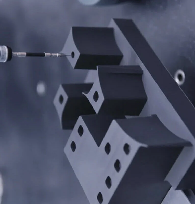
How Material Certification Influences HVAC Mold Design?
Material certification requirements influence HVAC injection mold design by imposing strict constraints on material selection, processing conditions, and final part performance, which must all be anticipated and integrated at the tooling stage. Certified materials—such as flame-retardant, UV-stabilized, or high-impact polymers—often exhibit specific rheological behaviors, shrinkage rates, and thermal sensitivities that differ from standard grades, requiring mold designers to adjust gate locations, runner balance, cooling channel layout, and venting strategies accordingly to ensure consistent filling and minimize internal stresses.
Core Principle: Material Constraints → Tooling Adaptation → Regulatory Compliance
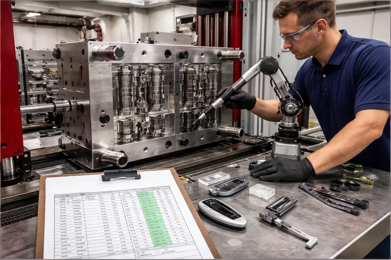
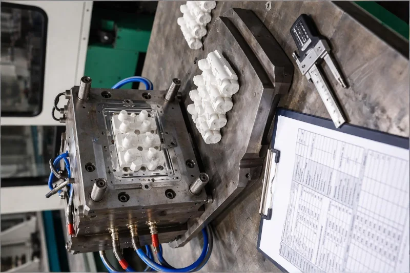
Design Adaptation & Compliance
Material Behavior & Tooling
Certified materials often exhibit specific rheological behaviors and shrinkage rates that differ from standard grades, requiring designers to adjust gate locations, runner balance, and cooling channel layout.
Design Impact: Venting strategies must be optimized to handle thermal sensitivities and ensure consistent filling while minimizing internal stresses.
Meeting Performance Standards
Certification standards define strict mechanical strength and safety thresholds. The mold must be engineered to produce parts with highly repeatable wall thickness, minimal warpage, and controlled fiber orientation.
Quality Focus: These dimensional factors directly affect test outcomes and the part's ability to consistently meet safety performance criteria.
Processing & Traceability
Certain certified materials have narrower processing windows or higher viscosity, increasing the risk of defects like short shots. Molds must be optimized for flow efficiency and heat transfer to prevent such issues.
Compliance Feature: Traceability requirements influence mold design to support consistent part identification, batch uniformity, and low variation across production cycles.
What Failure Modes Are Evaluated in HVAC Certification Testing Protocols?
HVAC certification testing protocols evaluate a wide range of failure modes to ensure that components can withstand mechanical loads, environmental stress, and long-term operational conditions without compromising safety or performance. These protocols assess structural integrity, thermal stability, and environmental resistance. By examining factors such as cracking, deformation, and material degradation, certification ensures that HVAC components maintain consistent performance under real-world operating conditions throughout their lifecycle.
Key Evaluation: Mechanical Loads → Environmental Stress → Safety Compliance → Long-term Reliability
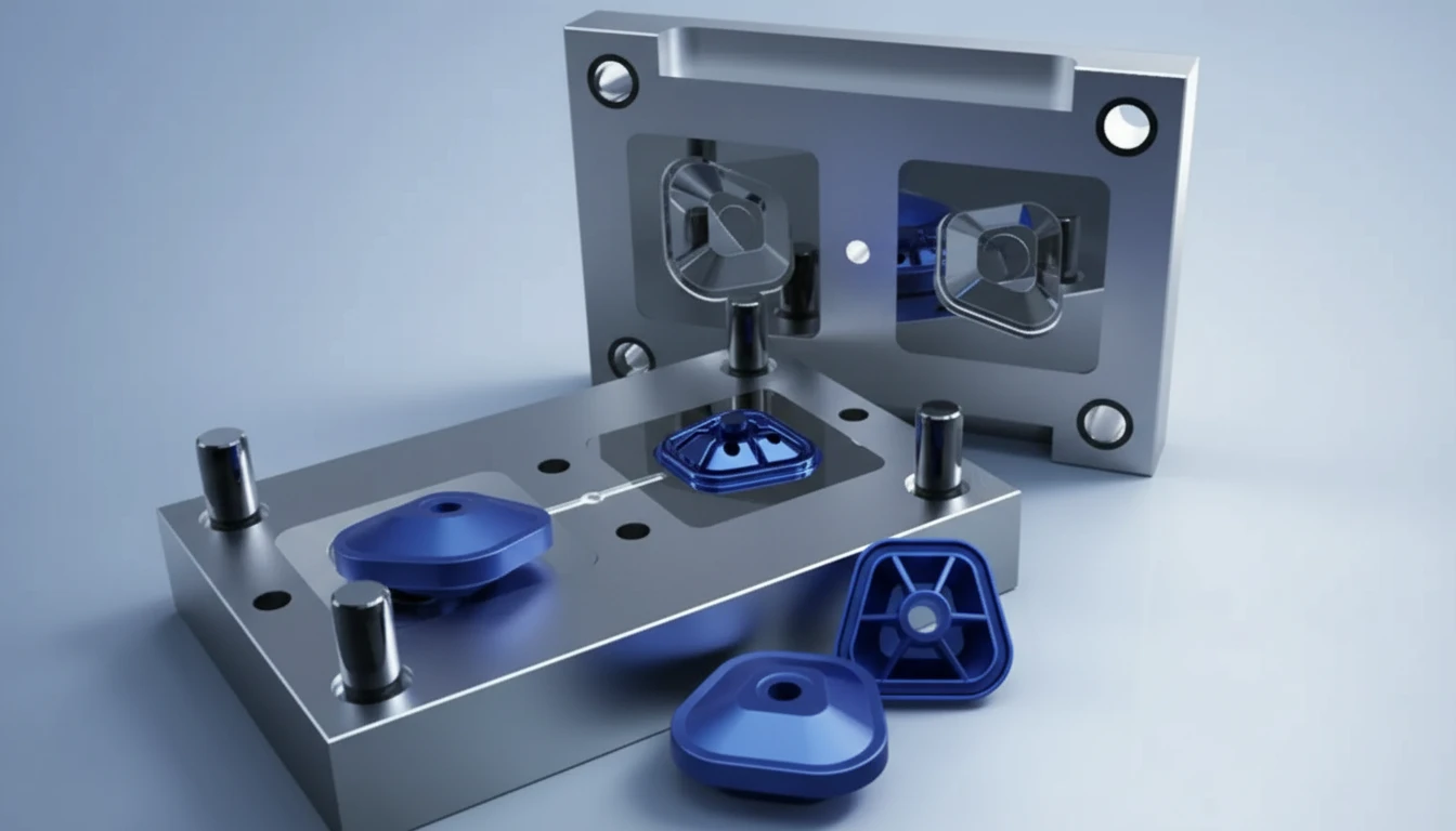
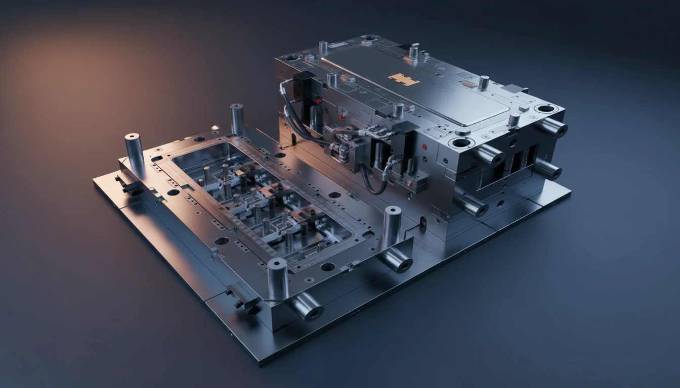
Structural & Thermal Failures
Structural Failure
Includes cracking, fracture, and deformation under static or dynamic loads. This is critical for housings, brackets, and load-bearing plastic parts.
Why it's crucial for HVAC: Ensures components can withstand physical stresses without collapsing or breaking, safeguarding system integrity.
Thermal Degradation
Repeated exposure to elevated temperatures or thermal cycling can lead to loss of stiffness, dimensional distortion, or material embrittlement.
Why it's important for HVAC: Vital for components near compressors or heat exchangers to prevent failure due to heat exposure.
Environmental Failure Modes
Assesses moisture ingress, corrosion interaction, and chemical exposure which may cause swelling, stress cracking, or surface deterioration.
Why it's important for HVAC: Ensures durability against harsh weather, humidity, and chemical agents found in operating environments.
Safety & Functional Failures
Flame-Related Failures
Examines ignition resistance, flame spread, and self-extinguishing behavior to ensure compliance with fire safety requirements.
Why it's crucial for HVAC: Protects property and lives by ensuring materials do not contribute to fire propagation.
Functional Failure Modes
Includes loss of sealing integrity, airflow leakage, or reduced vibration resistance, which directly impact system efficiency and noise control.
Why it's crucial for HVAC: Maintains optimal system performance, energy efficiency, and user comfort.
Long-Term Reliability
Evaluates creep deformation, fatigue under cyclic loading, and material aging to predict performance over the product lifecycle.
Why it's crucial for HVAC: Validates that components will perform consistently over years of operation, reducing replacement costs.
How is Long-Term Environmental Durability Validated?
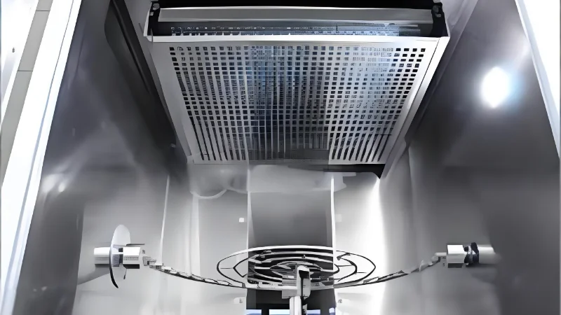
Long-term environmental durability in HVAC components is validated through accelerated aging protocols and multi-factor simulation tests that replicate years of field exposure within a controlled laboratory timeframe. These validations are designed to capture the cumulative effects of environmental stressors—such as cyclic temperature extremes, humidity fluctuations, atmospheric pollutants, and solar radiation—on material integrity and functional performance. Instead of relying on single-condition testing, durability assessment typically combines sequential or simultaneous exposure scenarios to evaluate how materials respond to synergistic degradation mechanisms.
Validation Focus: Accelerated Aging • Multi-factor Simulation • Stress-assisted Aging • Lifecycle Prediction
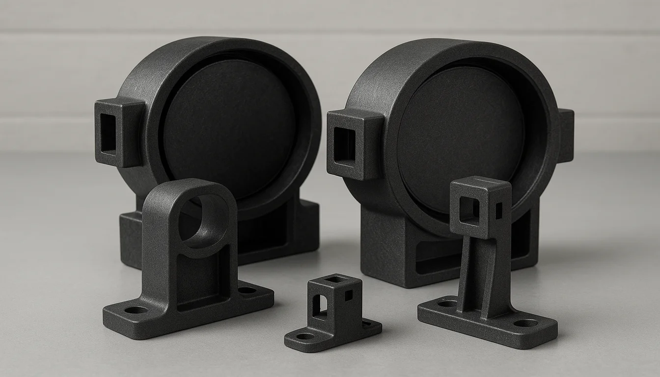
Accelerated Aging Protocols
These protocols replicate years of field exposure within a controlled laboratory timeframe to capture the cumulative effects of environmental stressors on material integrity.
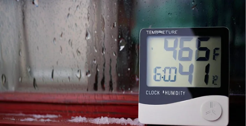
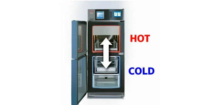
Multi-Factor Simulation Tests
Valutazione Specifica per HVAC.
Plastic Component Evaluation Metrics
Key evaluation metrics include retention of mechanical properties and dimensional stability after conditioning, as well as changes in surface morphology.
Advanced Validation & Criteria
Assemblies are subjected to ingress protection testing and stress-assisted aging where mechanical loads are applied during environmental exposure to simulate real operating conditions.
What are the Critical Differences Between UL, ISO, and HVAC-Specific Testing Frameworks?
UL standards are fundamentally rooted in safety compliance and risk mitigation, specifically targeting fire, electric shock, and mechanical injury hazards to ensure consumer protection. In contrast, ISO standards typically establish generic frameworks for quality management, environmental management, or general product specifications with a global consensus approach, focusing on consistency and process standardization. HVAC-specific testing frameworks, often governed by bodies like AHRI or ASHRAE, diverge by prioritizing operational performance metrics—such as SEER ratings, cooling capacity, and acoustic levels—over purely safety-oriented pass/fail criteria, ensuring the equipment functions efficiently within a system.
Key Frameworks: UL Standards • ISO Standards • HVAC-Specific Frameworks • Regulatory Acceptance • Evaluation Scope
| Framework | What It Is | Why It Matters |
|---|---|---|
| 🛡️ Focus & Primary Objectives | ||
| UL Standards | Fundamentally rooted in safety compliance and risk mitigation, specifically targeting fire, electric shock, and mechanical injury hazards. | Ensures consumer protection by establishing pass/fail criteria that prevent safety hazards, forming the baseline for product legality in North America. |
| ISO Standards | Establish generic frameworks for quality management, environmental management, or general product specifications with a global consensus approach. | Focuses on consistency and process standardization, ensuring that manufacturing processes are reliable and repeatable across international borders. |
| HVAC-Specific Frameworks | Governed by bodies like AHRI or ASHRAE, prioritizing operational performance metrics such as SEER ratings, cooling capacity, and acoustic levels. | Ensures the equipment functions efficiently within a system, verifying that performance claims match actual output rather than just meeting safety minimums. |
| ⚖️ Regulatory & Market Acceptance | ||
| UL Certification | Often mandatory for market entry in North America, functioning as a "de facto" legal requirement for electrical safety in many jurisdictions. | Critical for legal market access; products cannot be sold or installed without meeting these specific regional safety mandates. |
| ISO Certification | Serves as a voluntary business credential that signals process reliability and international compatibility. | Enhances brand reputation and operational efficiency but rarely grants permission to sell a specific product on its own. |
| HVAC-Specific Certification | Operates as industry-sealed guarantees of performance, ensuring equipment meets advertised efficiency claims. | Protects consumers from false performance claims and qualifies equipment for energy rebate programs, which generic safety standards do not address. |
| 🔬 Evaluation Scope & Methodology | ||
| UL Evaluation | Evaluates components based on their ability to contain failures and prevent hazards, often requiring specific spacings and flame-retardant materials. | Determines if a product can prevent catastrophic failure modes, focusing on containment and enclosure integrity. |
| ISO Evaluation | Looks at the component's dimensional tolerances and material consistency as part of a broader quality management system. | Ensures that every unit produced matches the design specifications, minimizing variations that could affect quality. |
| HVAC-Specific Evaluation | Metriche Basate sul Tempo:. | Assesses metrics critical for system thermodynamics that are irrelevant to safety certifications but essential for operational efficiency. |
How is Flame Retardancy Evaluated in HVAC Components?
For discrete plastic components used in HVAC units, such as fans, housings, and wire insulation, flame retardancy is quantitatively evaluated primarily through the UL 94 standard. For larger HVAC components like duct linings and paneling, the ASTM E84 (UL 723) Steiner Tunnel Test is used to concurrently evaluate flame retardancy and smoke density. These standards provide precise, time-based metrics and indices to ensure materials meet critical safety requirements in different applications.
Key Standards: UL 94 Vertical/Horizontal Burning • ASTM E84 Steiner Tunnel • Flame Spread Index • Smoke Density
UL 94 Vertical and Horizontal Burning Tests
This method measures the material's ability to extinguish a flame after being ignited, applicable to discrete plastic components used in HVAC units, such as fans, housings, and wire insulation.
Test Methodology:
- Vertical Burning Test (V-0, V-1, V-2): A specified flame is applied to the bottom of a vertically mounted specimen for two 10-second intervals.
- Quantitative Criteria: Includes the afterflame time (t1 and t2) for each specimen and the total afterflame time for the entire set.
- Drip Assessment: Evaluates the presence of flaming drips that ignite cotton indicator.
- Purpose: Provides a precise, time-based metric for comparing the flame retardancy of different polymer grades used in safety-critical parts.
Application Focus: Primarily used for smaller, discrete components where the material's self-extinguishing properties are critical for preventing fire propagation.
UL 94 V-0 Rating Criteria
The V-0 rating represents the highest standard for vertical burning under the UL 94 classification, requiring strict adherence to specific time limits and burn behaviors.
Performance Requirements:
- Total Afterflame Time: Must not exceed 50 seconds for a set of five specimens.
- Individual Burn Time: No individual specimen can burn for more than 10 seconds after the second ignition.
- Flaming Drips: Must not ignite the cotton indicator placed below the specimen.
- Significance: Ensures rapid self-extinguishing behavior to minimize fire risk in HVAC equipment.
Critical Distinction: Lower ratings like V-1 and V-2 allow for longer burn times, with V-2 specifically permitting flaming drips that may ignite cotton, posing a different risk profile.
ASTM E84 Steiner Tunnel Test
For larger HVAC components like duct linings, insulation boards, and paneling, flame retardancy and smoke density are concurrently evaluated using this standard (also known as UL 723).
Test Configuration:
- Specimen Size: Exposes a 25-foot long specimen to a controlled flame in a horizontal tunnel.
- Surface Burning: Quantifies the surface burning characteristics of the material.
- Dual Measurement: Concurrently evaluates both flame spread and smoke density.
- Scope: Essential for materials used in air handling systems where surface spread is a major hazard.
Scale Difference: Unlike UL 94 which tests small discrete parts, ASTM E84 evaluates the fire performance of large surface areas typical of ductwork and building panels.
ASTM E84 Quantitative Metrics
The test results are quantified through specific indices that allow for direct comparison of material performance against established benchmarks.
Key Metrics:
- Flame Spread Index (FSI): Derived by comparing the area under the flame spread-versus-time curve of the test material to established standards.
- Reference Benchmarks: Red oak is assigned an FSI of 100, while inorganic cement board serves as the baseline with an FSI of 0.
- Smoke Density: Quantitatively evaluated by measuring the attenuation of a light beam passing through the exhaust.
- Classification: Materials are rated as Class A, B, or C based on their FSI scores, crucial for building code compliance.
Interpretation: Lower FSI values indicate better flame resistance, while lower smoke density measurements indicate reduced hazard to occupants during a fire event.
Comparison at a Glance
| Standard | Key Metric | Application |
|---|---|---|
| UL 94 | Afterflame time (seconds), Flaming drips | Discrete components: fans, housings, wire insulation |
| ASTM E84 | Flame Spread Index (FSI), Smoke Density | Large components: duct linings, insulation boards, paneling |
Significance of Quantitative Evaluation
These testing frameworks provide objective, measurable data rather than subjective observations:
- Time-Based Metrics: Tipo di Test.
- Comparative Indices: ASTM E84 compares materials against known standards (Red Oak, Cement Board), providing a relative performance scale.
- Safety Compliance: These quantitative results form the basis for regulatory approvals and material selection in critical HVAC infrastructure.
- Hazard Identification: Measuring both flame spread and smoke density addresses the primary life safety hazards during fire incidents.
What Testing Methods are Used to Validate Airflow Integrity and Structural Sealing?
The primary method used to validate airflow integrity for Air Handling Units (AHUs) and ventilation casings is the casing leakage test, often conducted in accordance with standards like AMCA 260 or Eurovent. For ductwork distribution systems, specialized duct leakage testing is employed using devices like duct blasters, adhering to standards such as SMACNA or DW/143. These testing methods quantitatively measure the air volume required to maintain specific pressure levels, ensuring that structural sealing is effective and energy loss is minimized.
Key Methods: Casing Leakage Test • Duct Leakage Test • AMCA 260 • SMACNA • Pressure Testing
Casing Leakage Testing for AHUs
The primary method used to validate airflow integrity for Air Handling Units (AHUs) and ventilation casings, often conducted in accordance with standards like AMCA 260 or Eurovent.
Testing Procedure:
- Complete Seal: The unit is sealed completely to isolate the internal environment.
- Pressurization: Internal pressure is increased to a specific static pressure level (typically 1 to 6 inches w.g.) depending on application class.
- Flow Measurement: The volume of air required to maintain this pressure is measured precisely using calibrated flow meters.
- Direct Equivalence: This volume equates directly to the leakage rate, providing a quantitative assessment of integrity.
Why It Matters: Excessive casing leakage reduces system efficiency by losing conditioned air and indicates potential structural sealing defects at joints or access doors.
Quantitative Validation & Defect Identification
This validation is critical because excessive leakage not only reduces efficiency but also serves as a diagnostic tool for structural integrity issues.
Key Indicators:
- Efficiency Loss: Loss of conditioned air directly impacts system performance and energy consumption.
- Structural Defects: High leakage rates indicate defects at joints, access doors, or panel connections.
- Environmental Control: Identifying leaks prevents compromise of the controlled environment.
- Data-Driven Repairs: Quantitative results allow for targeted maintenance and sealing improvements.
Critical Insight: The test provides precise data that correlates directly to potential failure points in the structural assembly, moving beyond simple pass/fail assessments.
Ductwork Leakage Testing Protocols
For validating the structural sealing of ductwork distribution systems, specialized testing is employed using devices like duct blasters or calibrated fans, adhering to standards such as SMACNA HVAC Air Duct Leakage Test or DW/143.
Methodology:
- Section Isolation: A specific section of ductwork is isolated by sealing all diffusers and grilles.
- Pressurization: The duct is pressurized to a test pressure that reflects its actual operating conditions.
- Leakage Rate Measurement: The airflow required to sustain that pressure is measured as the leakage rate.
- Class Comparison: Results are compared against maximum allowable rates for design classes (e.g., Seal Class A, B, or C).
Equipment Used: Duct blasters and calibrated fans are essential tools for applying controlled pressure and measuring the resulting airflow accurately.
Validation of Sealing Effectiveness
This method ensures that sealing methods applied to critical junctions are effective in preventing energy loss and maintaining pressure hierarchy.
Key Focus Areas:
- Transverse Joints: Ensuring connections between duct sections are airtight.
- Longitudinal Seams: Verifying the integrity of seams running along the duct length.
- Penetrations: Checking seals around dampers, access doors, and other penetrations.
- Pressure Hierarchy: Maintaining the designed pressure differences within the building.
Outcome: Confirms that the ductwork system meets design specifications for airtightness, preventing energy loss and ensuring efficient operation.
Comparison at a Glance
| Test Type | Standard | Test di integrità dell'assemblaggio HVAC |
|---|---|---|
| Casing Leakage | AMCA 260, Eurovent | Air Handling Units (AHUs), Ventilation casings |
| Duct Leakage | SMACNA, DW/143 | Ductwork distribution systems, Isolated sections |
Significance of Airflow Integrity Testing
These testing frameworks provide essential validation for system performance and safety:
- Energy Conservation: Identifying and rectifying leaks prevents significant energy loss associated with conditioned air escaping.
- Performance Verification: Ensures that the system operates according to design specifications regarding pressure and flow.
- Quality Assurance: Validates the quality of installation, particularly at joints, seams, and access points.
- Environmental Control: Critical for maintaining pressure hierarchies in sensitive environments like cleanrooms or isolation wards.
Sembra strutturalmente solido
Process variations in injection molding affect certification outcomes at a microstructural and statistical level rather than just causing visible defects. Certification bodies do not evaluate single parts in isolation; they assess whether a process can consistently produce parts whose performance distributions remain within defined limits under standardized tests (thermal cycling, pressure loading, flammability, etc.).
Certification Focus: Microstructural Integrity • Statistical Consistency • Process Stability
Microstructural & Physical Variation Analysis
Understanding how process parameters influence molecular structure is critical for predicting certification success. Here is how specific variations impact performance.
Molecular Orientation Variations
Fluctuations in parameters like melt temperature or shear rate alter molecular orientation and chain entanglement density within the polymer.
Process Mechanism:
- Fluctuations in melt temperature or shear rate
- Changes in molecular orientation
- Altered chain entanglement density
- Flow direction dependent properties
Certification Impact:
- Direct alteration of anisotropy in mechanical properties
- Tensile/impact strength vary by orientation
- Pass tests in one direction but fail in another
- Non-repeatable outcomes across samples
Anisotropy & Performance Consistency
Changes in molecular structure create direction-dependent properties, complicating standardized testing where uniform performance is assumed.
Structural Changes:
- Molecular orientation creates weak axes
- Inconsistent chain entanglement
- Variable creep behavior
- Directional stress concentrations
Testing Outcome:
- Component passes tests in specific orientation
- Failure occurs when stressed in weak direction
- Unpredictable field performance
- Inconsistent certification sample results
Residual Stress Gradients
Variations in cooling rate affect residual stress gradients through the wall thickness, leading to failures during thermal or pressure testing.
Cooling Mechanism:
- Faster cooling at mold surface vs. slower core
- Differential shrinkage through thickness
- Hidden internal stress accumulation
- Part geometry affecting cooling uniformity
Delayed Failure Mode:
- Manifests during thermal aging tests
- Deformation under pressure loading
- Uneven stress relaxation at high temp
- Inconsistency between inspection and test results
Dimensional Compliance vs. Structural Failure
Parts that appear dimensionally compliant at room temperature can deform or crack under elevated temperature certification conditions.
Initial Inspection:
- Dimensions meet specifications at room temp
- No visible distortion or defects
- Passes initial visual checks
- Appears structurally sound
Passaggio da Windows Ideale a Windows Robusto
- Internal stresses relax unevenly
- Deformation under thermal load
- Cracking during pressure hold tests
- Failure during long-term aging protocols
Statistical Capability & Consistency Control
Statistical Acceptance Challenges
Distribution Risks:
- Certification is a statistical acceptance problem
- Increased process variation widens distribution curve
- Average properties may meet specs
- Wider variance increases out-of-limit probability
Sampling Impact:
- Higher probability of sampling non-conforming parts
- Critical risk in multi-sample destructive tests
- Failure to meet defined performance limits
- Invalidates certification attempts
Process Stability Metrics (Cp/Cpk)
Process Instability:
- Slight instability in packing pressure
- Fractional percent shifts in shrinkage
- Variation across multiple cavities or cycles
- Produces wider variance band
Capability Thresholds:
- Reduces Cp/Cpk below certifiable thresholds
- Failure due to insufficient stability
- Inability to guarantee repeatability
- Not caused by single defect, but systemic variation
Batch-to-Batch Variability & Traceability
Transient Disturbances:
- Material moisture fluctuation
- Screw recovery inconsistency
- Short-term temperature drift
- Difficult to detect via routine inspection
Audit Consequences:
- Evident during certification audits
- Requires traceability across production lots
- Inter-batch variability leads to conflicting results
- Invalidates certification if consistency is unproven
What are the Challenges of Scaling Certification from Prototype to Mass Production?
Scaling certification from prototype to mass production is fundamentally challenging because the conditions under which a prototype is qualified are rarely identical to those in full-scale manufacturing. Certification bodies evaluate not just design validity but process reproducibility at scale. The transition introduces spatial and temporal variations that were not present during initial testing, requiring a shift from ideal processing conditions to robust processing windows.
Key Challenge: Reproducibility at Scale • Process Variability • Compliance Consistency


Process & Tooling Challenges
Mold Scaling & Cavity Imbalance
Prototypes use single-cavity molds with stable short runs. Mass production uses multi-cavity molds, introducing spatial variations.
Why it's crucial: Cavity-to-cavity imbalance, pressure drop differences, and thermal gradients create systematic property deviations between parts.
Shift from Ideal to Robust Windows
Rischio di Fallimento:.
Why it's crucial: Expansion increases risk of falling near or beyond acceptable performance limits defined during certification.
Equipment & Maintenance Variability
Production molds are complex and subject to uneven wear, cooling inefficiencies, and maintenance-related drift over time.
Why it's crucial: Machine differences like screw design and clamping force stability create discrepancies requiring re-optimization.
Material & Compliance Challenges
Material Consistency at Scale
Prototypes use limited, well-characterized batches. Mass production involves different lots, suppliers, and storage conditions.
Why it's crucial: Variations in molecular weight and additive dispersion can shift properties, potentially invalidating safety margins.
Performance Inconsistency
A design certified under tight controls may show marginal compliance under real production variability.
Why it's crucial: Critical metrics like dimensional stability, creep, and thermal deformation resistance may vary between lots.
Statistical Sampling & Audits
Mass production demands ongoing compliance verification, batch sampling, and process capability demonstration.
Why it's crucial: Drift in parameters or unexplained variation can trigger re-certification or suspension, making scale-up a continuous challenge.
Comparison: Prototype vs. Mass Production Conditions
| Factor | Prototype Phase | Mass Production Phase |
|---|---|---|
| Tooling | Single-cavity molds, easier thermal control. | Multi-cavity molds, thermal gradients & wear issues. |
| Processing Windows | Narrow, optimized parameters to guarantee passing. | Wider windows required to accommodate variability. |
| Material Source | Limited batches, well-characterized, pre-conditioned. | Multiple lots/suppliers, variable storage conditions. |
| Variability Source | Minimal; focused on design validity. | Spatial (cavity imbalance) & Temporal (drift over time). |
| Certification Focus | Design validity, limited sample testing. | Process reproducibility, ongoing audits & traceability. |
Frequently Asked Questions
Explore the critical challenges in certification testing for manufactured components. Understand how worst-case conditions are simulated by combining material property limits and environmental stressors. Learn why statistical confidence is crucial for acceptance, how multi-physics interactions complicate validation, and the methods used to detect hidden defects that may not manifest during initial testing but could lead to field failures.
Key Focus: Worst-Case Simulation • Statistical Confidence • Multi-Physics Interactions • Hidden Defect Detection
How are Worst-Case Conditions Defined and Simulated in Certification Testing?
Testing focus: Constructing extreme but plausible operating scenarios.
+
How are Worst-Case Conditions Defined and Simulated in Certification Testing?
Testing focus: Constructing extreme but plausible operating scenarios.
Key Insights:
Definition & Simulation:
Certification testing does not rely on nominal operating conditions; instead, it intentionally constructs worst-case scenarios that combine upper and lower bounds of material properties, dimensional tolerances, and environmental stresses.
Implementation Methods:
This includes stacking tolerances (max wall thickness + lowest thermal conductivity), applying simultaneous stressors (high temperature + pressure + humidity), and selecting samples from statistically unfavorable positions (e.g., end-of-run or edge cavities).
Critical Challenge:
The challenge lies in ensuring that these conditions are not theoretical extremes but are still representative of plausible production variation. If worst-case modeling is inaccurate, certification results may overestimate real-world reliability, leading to latent field failures.
What Role does Statistical Confidence Play in Certification Test Acceptance?
Testing focus: Population consistency and risk management.
+
What Role does Statistical Confidence Play in Certification Test Acceptance?
Testing focus: Population consistency and risk management.
Key Insights:
Decision Basis:
Certification decisions are rarely based on pass/fail of individual samples; they are derived from statistical confidence levels that the entire population meets requirements.
Statistical Parameters:
This involves defining acceptable quality limits (AQL), confidence intervals, and sample sizes that balance risk between manufacturer and certifying body.
Failure Risk:
Variabilità di Produzione.
How do Multi-Physics Interactions Complicate Certification Testing?
Testing focus: Coupled physical effects and failure modes.
+
How do Multi-Physics Interactions Complicate Certification Testing?
Testing focus: Coupled physical effects and failure modes.
Key Insights:
Coupled Effects:
In real certification environments, components are subjected to coupled physical effects rather than isolated loads. Thermal expansion, mechanical stress, fluid pressure, and chemical exposure interact in non-linear ways.
Interaction Examples:
Thermal cycling can accelerate crack propagation initiated by mechanical stress, while humidity may reduce material stiffness and alter stress distribution, often amplifying failure modes that would not appear under single-factor testing.
Testing Difficulty:
Certification testing must therefore replicate these coupled conditions, but accurately reproducing such interactions in a controlled and repeatable manner remains a major technical challenge.
How are Hidden Defects Detected When They Do Not Manifest in Initial Testing?
Testing focus: Latent defects and long-term failure risks.
+
How are Hidden Defects Detected When They Do Not Manifest in Initial Testing?
Testing focus: Latent defects and long-term failure risks.
Key Insights:
Nature of Hidden Defects:
Some defects—such as micro-voids, weak weld lines, or residual stress concentrations—may not immediately affect performance but can evolve into critical failures under prolonged or cyclic loading.
Detection Methods:
Certification testing addresses this through methods such as fatigue testing, pressure cycling, and non-destructive evaluation (e.g., ultrasonic or X-ray inspection).
Correlation Challenge:
The difficulty lies in correlating these indirect detection methods with actual failure risk, as not all detected anomalies will lead to failure, and not all critical defects are easily detectable.