
Функциональная интеграция for HVAC Components
HVACore delivers precision plastic blow molding solutions for HVAC tanks, ducts, and complex housings. With 20+ years of OEM/ODM expertise and 45 advanced production lines, we manufacture high-performance components that meet the demanding requirements of global HVAC systems.
Table of Contents
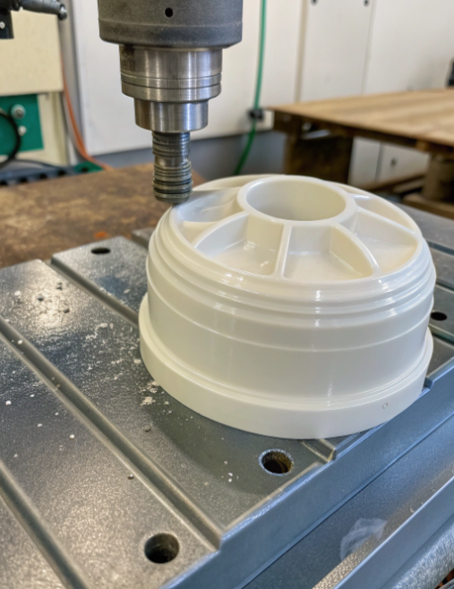
What is HVAC Blow Molding?
HVAC blow molding components utilize an integrated hollow structure, which reduces weight while maintaining structural integrity. This process supports the creation of complex geometries and allows for a diverse range of materials to suit various environmental conditions. Common applications include air duct systems, condensate drainage solutions, and protective equipment housings. By minimizing material usage and simplifying assembly steps, blow molding offers a cost-effective and versatile manufacturing solution for a wide array of demanding HVAC applications across commercial, industrial, and residential sectors.
Key Considerations: Parison Formation • Inflation Process • Mold Design • Material Selection • Cooling Cycle
Blow Molding Process
Blow molding is a specialized manufacturing process used to create hollow plastic parts and containers. This versatile technique involves melting plastic and forming it into a parison (a tube-like shape), which is then inflated like a balloon inside a mold cavity to take the desired shape.
The process begins with plastic pellets being melted and extruded into a hollow tube. This parison is then clamped into a mold and inflated with compressed air, forcing the plastic to expand and conform to the mold's interior contours. After cooling and solidification, the mold opens to release the finished product.
HVAC Blow Molding
HVAC blow molding represents a highly specialized branch of the blow molding manufacturing process, specifically engineered for producing essential critical components within heating, ventilation, and air conditioning systems. This innovative advanced molding technique is primarily utilized to manufacture various shapes and sizes of plastic ductwork, piping systems, air distribution components, and connection fittings that serve as the critical fundamental backbone of modern air circulation and climate control infrastructure. These durable precision-engineered components offer superior thermal insulation properties.
Key Benefits of HVAC Blow Molding
One-piece construction reduces connection points and air leakage
Lightweight materials simplify installation and reduce structural load
Corrosion resistance extends system lifespan in harsh environments
How to Optimize HVAC Blow Molding Duct Design & Performance?
Blow molded ducts are extensively used in automotive air conditioning, building HVAC, and home appliance systems. The design objectives are to achieve high efficiency, lightweight construction, reliability, and cost-effectiveness while meeting functional requirements. We analyze these goals through three key dimensions: aerodynamics, lightweight & structural strength, and integrated design. Aerodynamic optimization focuses on internal flow path, elbow design, and branching junctions to maximize flow efficiency. Lightweight design utilizes hollow double-wall structures, reinforcement ribs, and advanced materials like multi-layer co-extrusion and foam blow molding. Integrated design combines functional components, eliminates leak points, and simplifies the supply chain by replacing multiple assemblies with a single blow molded part.
Key Focus Areas: Aerodynamic Design • Lightweight Structure • Material Innovation • Functional Integration
1. Aerodynamic Design: Maximizing Flow Efficiency Under Blow Molding Constraints
Internal Flow Path Optimization
Elbow Design Challenges
During blow molding, parisons at corners experience uneven wall thickness due to gravity, inflation pressure, and temperature variations. Outer side becomes thinner while the inner side thickens, affecting both structural strength.
- CAE simulation for precise parison wall thickness distribution
- Integrated flow guide ribs reduce 90° elbow resistance by 40-70%
Branching & Junction Optimization
Y-type junctions with branch angles less than 30° replace traditional T-type right-angle splits. Smooth transitions eliminate sharp corners and depressions that generate vortices and noise.
- Internal flow distribution fins for precise flow control
- Mirror-polished mold surfaces reduce friction coefficients
- High-flow materials (PP, PE) ensure smooth surface finish
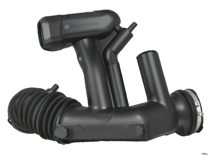
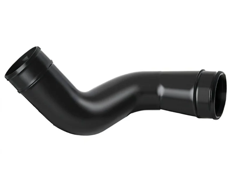
2. Lightweight & Structural Strength: Maximizing Blow Molding Advantages
Hollow Double-Wall & Reinforcement Design
Inner and outer thin walls connected by internal ribs create stable I-beam or truss structures. Ribs are positioned along primary stress directions (typically axial) with increased density at corners and flange connections.
- Main wall thickness: 1.5-3.0mm
- Rib thickness: 0.5-0.8× main wall thickness
- Elliptical rib cross-sections reduce stress concentration
Advanced Material Applications
Multi-layer co-extrusion blow molding creates composite ducts with specialized layer functions: weather-resistant outer layer, recycled material middle layer, barrier layer (EVOH), and smooth inner layer.
- Foam blow molding reduces weight by 10-30%
- LFT-PP (>5mm fiber length) for high-strength applications
- PA6+GF for high-temperature engine bay ducts
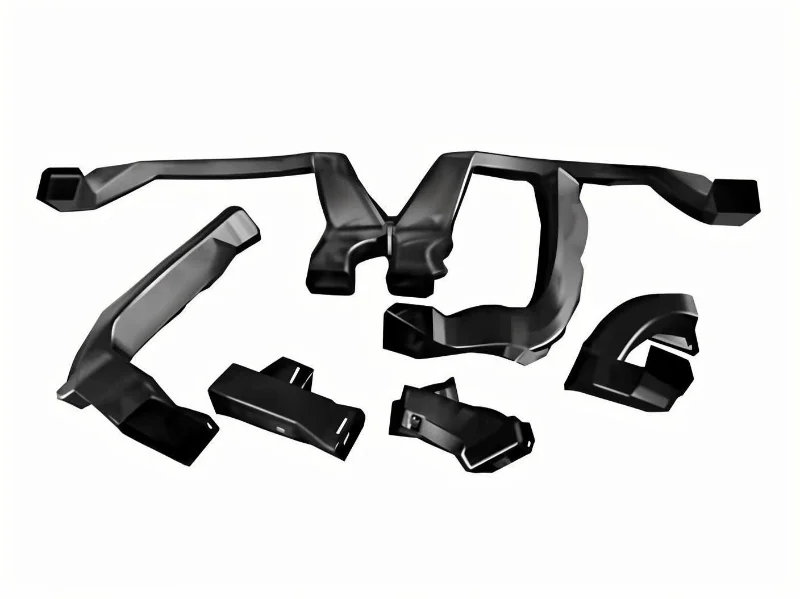
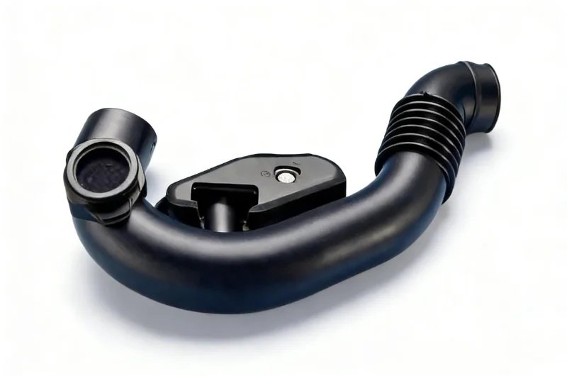
3. Integrated Design: The Ultimate Value of Blow Molding Technology
Functional Integration
Может быть совместно экструдирован с пеноматериалами в процессе выдувного формования, устраняя тепловые мосты.
Leak Elimination
Seamless flow paths from inlet to outlet eliminate welding and adhesive joints, ensuring long-term airtightness.
Supply Chain Impact
Single blow molded part replaces 5-10 component assemblies, dramatically simplifying BOM, inventory, and logistics.
Production Efficiency Revolution
Transformation from multi-component assembly lines to single-piece inspection and packaging reduces production cycle time, increases automation levels, and significantly lowers labor costs while ensuring consistent quality through mold-based production.
Why HVAC Choose Blow Molding?
Blow molding offers substantial advantages for manufacturing HVAC tanks, combining cost efficiency, design flexibility, and energy savings. This manufacturing process enables the creation of complex geometries with integrated features while optimizing material usage and production costs. Modern blow molding technologies have evolved to deliver superior structural integrity, consistent wall thickness, and reduced environmental impact, making it an ideal choice for medium to high-volume production of HVAC components.
Key Advantages: Cost Efficiency • Complex Geometries • Energy Savings • High-Volume Production
Cost Efficiency
Material Optimization
Minimizes waste by using only necessary plastic, with excess material typically recyclable. Reduces raw material costs by up to 30% compared to other methods.
High-Volume Production
Rapid production with cycle times often less than one minute per part, reducing labor costs and enabling economies of scale.
Energy Efficiency
Modern equipment incorporates energy-saving features such as variable frequency drives and optimized heating systems.
Complex Geometries
Complex Shapes
Creates tanks with intricate contours, internal chambers, and integrated features that optimize space utilization within HVAC systems.
Uniform Wall Thickness
Advanced techniques ensure consistent wall thickness throughout the tank, critical for structural integrity and pressure resistance.
Integrated Features
Incorporates mounting points, connection ports, reinforcement ribs, and fluid channels directly into the tank design.
Energy Efficiency in Production
Energy-Efficient Equipment
Newer machines incorporate variable frequency drives, regenerative heating systems, and optimized cooling that reduce energy consumption by up to 30%.
Reduced Processing Requirements
Low processing temperatures and short cycle times contribute to lower overall energy use compared to alternative manufacturing methods.
Sustainable Manufacturing
Lower energy consumption contribute to reduced environmental impact.
Blow Molding Benefits for HVAC Applications
Cost Reduction
Lower material, labor, and energy costs compared to alternative manufacturing methods
Design Flexibility
Create complex shapes and integrated features that optimize space and functionality
Structural Integrity
Consistent wall thickness ensures pressure resistance and durability in HVAC applications
Environmental Benefits
Reduced material waste and energy consumption contribute to a smaller environmental footprint
What are the Applications of Blow Molding in HVAC?
HVAC blow molding products feature an integrated hollow structure that reduces weight while maintaining structural integrity. The manufacturing process enables complex geometries and seamless one-piece constructions, with material options suitable for various environmental conditions. These components are implemented in multiple HVAC system applications, including air duct systems that optimize airflow efficiency, condensate drainage solutions that prevent water damage, protective equipment housings, and application-specific engineered solutions. The technology delivers performance advantages through reduced material usage and assembly time, with design versatility applicable across commercial, industrial, and residential HVAC sectors.
Key Applications: Air Duct Systems • Condensate Drainage • Equipment Housings • Custom Solutions
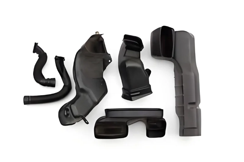
Air Duct Systems
Products: Round/oval supply ducts, return ducts, elbows, tees, reducers, etc.
- • Excellent Airtightness: Seamless construction prevents air leakage, improving system efficiency by up to 30%
- • Lightweight: 50-70% lighter than traditional metal ducts, significantly reducing transportation and installation costs
- • Smooth Interior: Low air resistance, reduced noise, and minimized energy loss
- • Integrated Insulation: Can be co-extruded with foam materials during blow molding, eliminating thermal bridging
Условия использования
Products: Condensate pipes, drain pipes, P-traps, collection trays, and associated components.
- • Absolute Corrosion Resistance: Made from high-grade PP, PE and other engineering plastics that never rust, perfect for acidic condensate environments
- • Anti-Clogging Design: Smooth interior prevents scale buildup, can be designed with steep gradients or integrated long pipes to reduce joints and potential leaks
- • Easy Installation: Flexible connections adapt to complex installation environments, shortening construction time and reducing labor costs

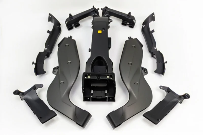
Equipment Housings & Functional Components
Products: Fan coil unit housings, air handler casings, heat pump unit shells, expansion tanks, buffer tanks.
- • Integrated Structure: Can form mounting brackets, connection ports, and access panels in one piece, reducing subsequent processing
- • Excellent Thermal and Acoustic Insulation: Effectively reduces equipment noise and heat loss, enhancing user experience
- • Superior Weather Resistance: With anti-UV additives, can be used long-term in harsh outdoor environments without fading or aging
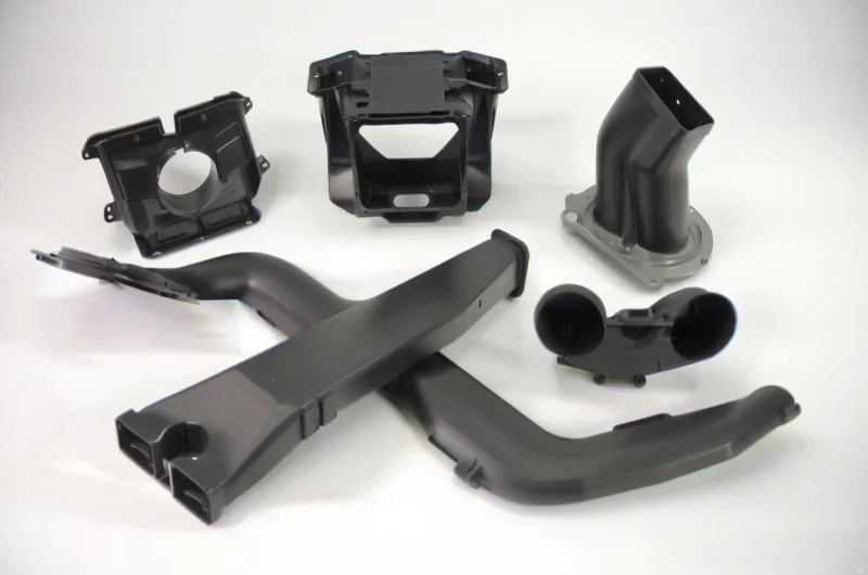
Special Applications & Custom Solutions
Products: Muffler housings, silencer elbows, special fluid transport pipes, automotive/train air conditioning ducts.
- • Highly Customizable: We provide one-stop customization services from material selection and structural design to mold development based on customer drawings
- • Complex Geometric Forming: Blow molding can achieve complex hollow shapes that are difficult to accomplish with other methods, meeting special functional requirements
What Materials are Used in HVAC Blow Molding?
Selecting the appropriate plastic material for HVAC blow molding tanks is crucial as it directly impacts product performance, durability, and cost-effectiveness. Our comprehensive material comparison covers seven commonly used plastics in HVAC applications, each with unique properties suited for specific requirements. From HDPE's excellent chemical resistance and cost-effectiveness for condensate pans to PC's superior impact strength for protective components, our material selection guide helps you make informed decisions based on environmental conditions, mechanical requirements, regulatory compliance, and budget constraints. With our expertise in HVAC blow molding, we ensure optimal material selection that balances performance, longevity, and economic considerations for your specific application needs.
Key Materials: HDPE • PP • PET • PC • PVC • EVOH • TPE
Materials Comparison Table
| Material Name | Material Type | Key Characteristics | Typical HVAC Applications |
|---|---|---|---|
| HDPE | Polyethylene | High density, chemical resistant, impact resistant, low cost, good low temperature performance | Condensate pans, drain pipes, ventilation ducts, liquid storage tanks |
| Следующие сценарии применения демонстрируют, где | Polypropylene | Lightweight, good heat resistance (100-140°C), excellent chemical resistance, harder than PE | Duct systems, fan housings, hot water tanks, components requiring sterilization |
| PET | Polyethylene Terephthalate | High transparency, good gas barrier properties, high strength, recyclable | Pressure vessels, transparent observation windows, filter housings |
| Термопласты для компонентов систем отопления, вентиляции и кондиционирования | Polycarbonate | Extremely high impact strength, transparent, heat resistant, dimensionally stable | High-strength transparent components, protective covers, electrical housings |
| PVC | Polyvinyl Chloride | Excellent chemical resistance, good flame retardancy, low cost | Exhaust pipes, wire sheaths, corrosion-resistant pipes |
| EVOH | Ethylene-Vinyl Alcohol Copolymer | Excellent gas barrier properties (especially oxygen), transparent | Barrier layer in multilayer structures (e.g., refrigerant-resistant reservoirs) |
| TPE | Thermoplastic Elastomer | Soft, good elasticity, comfortable touch, weather resistant, recyclable | Seals, hoses, shock-absorbing components, handles requiring tactile feel |
Material Selection Key Considerations
Usage Environment
Проектирование и производство пресс-форм с высокой точностью.
Mechanical Performance Requirements
How much pressure and impact do components need to withstand? Is rigidity or flexibility required? For example, PC and TPE represent high rigidity and high elasticity respectively.
Regulations & Compliance
Does the material in question comply with relevant fire safety (flame retardancy ratings), environmental regulations (RoHS), and food contact standards?
Cost & Processability
Material cost and processing difficulty (drying requirements, mold design requirements) are important economic factors. HDPE and PP are common choices due to their cost-effectiveness and ease of processing.
What are the Advantages and Disadvantages of Using Plastic Blow Molding in HVAC Systems?
Plastic blow molding in HVAC systems offers significant advantages including cost efficiency, design flexibility, and excellent performance characteristics suited for HVAC applications. However, it presents notable challenges such as mechanical and thermal limitations, material considerations like UV degradation and flammability, and manufacturing constraints including high initial tooling costs and limited dimensional accuracy. While the process enables creation of complex hollow structures like air ducts and tanks with integrated features, the material limitations and tooling investments make it best suited for medium to high-volume production where design considerations are carefully balanced against performance requirements.
Key Balance: Design Flexibility & Cost Efficiency vs. Material Limitations & Tooling Investment
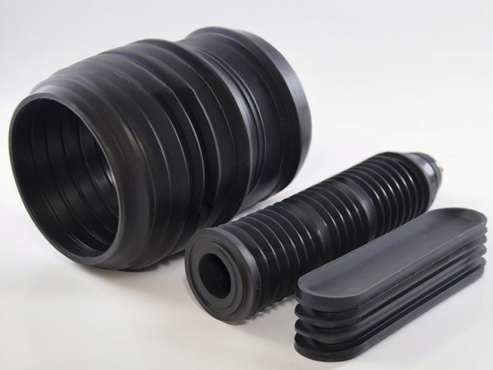
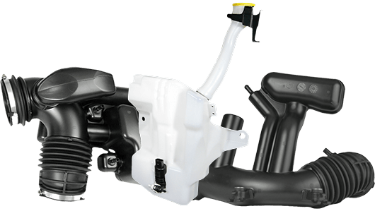
Advantages
Significant Cost Efficiency & Production Economics
The process is inherently material-efficient with minimal waste that can be directly recycled. Fast production cycles (often under 60 seconds) lower per-part labor costs and enable economies of scale. Integrated design eliminates the need for multiple components, welding, adhesives, or fasteners, dramatically reducing assembly time and potential failure points.
Why it's crucial for HVAC: The HVAC industry requires cost-effective components for mass production. Blow molding provides the economic advantage needed for competitive pricing in air ducts, water tanks, and other components.
Unmatched Design Freedom & Integration
The process easily produces complex shapes, double-wall structures, and internal chambers that would be prohibitively expensive with other methods. Seamless construction ensures superior airtightness and leak-proof performance. Functional elements like handles, reinforcement ribs, and connection ports can be incorporated directly into the mold design.
Why it's important for HVAC: Modern HVAC systems require components that maximize space utilization within tight unit enclosures while maintaining optimal performance. Blow molding delivers these custom-fit solutions efficiently.
Superior Performance Characteristics
Unlike metals, plastics like PP, PE, and PVC are inherently immune to rust and corrosion. They can withstand exposure to condensate and cleaning chemicals without degrading. Components are typically 50-70% lighter than metal counterparts, reducing shipping costs and structural load. The hollow structure provides excellent thermal and acoustic insulation.
Why it's important for HVAC: These performance characteristics directly address key HVAC concerns: longevity in harsh environments, installation efficiency, and energy efficiency through insulation properties.
Disadvantages
Mechanical & Thermal Performance Limitations
Plastics generally have lower tensile strength, impact resistance, and overall structural rigidity compared to metals. They have a limited operating temperature range and can soften at sustained elevated temperatures or become brittle at extremely low temperatures. Consequently, standard blow molded tanks typically have lower pressure ratings than fabricated metal parts.
Why it's crucial for HVAC: These limitations require careful material selection and design considerations, especially for components exposed to temperature extremes or pressure requirements.
Material & Environmental Considerations
Many plastics are susceptible to UV degradation over extended sun exposure, requiring specialized UV stabilizers or protective outer layers for outdoor applications. Most plastics are inherently combustible, necessitating appropriate flame retardant additives to meet safety standards. Some plastics exhibit gas or vapor permeability over extended time periods, which may be a critical consideration for certain sealed applications.
Why it's crucial for HVAC: These material considerations directly impact component longevity and safety compliance, especially for outdoor units or components exposed to sunlight.
Manufacturing & Tooling Constraints
The cost of designing and manufacturing precision blow molds is significant, making the process economically viable only for medium to high-volume production. Achieving tight tolerances can be challenging, and controlling uniform wall thickness requires advanced programming and design expertise.
Why it's crucial for HVAC: The high initial investment and technical requirements make blow molding less suitable for small production runs or applications requiring extremely precise dimensions.
What is the HVAC Blow Molding Process?
HVAC blow molding is a specialized manufacturing process that creates hollow plastic components for heating, ventilation, and air conditioning systems. The process involves six key stages: material preparation, parison extrusion, mold closing and inflation, cooling, part ejection, and post-processing. This technique enables the production of lightweight, durable, and leak-free parts with complex geometries that traditional manufacturing methods cannot achieve efficiently. The technology is particularly valued for its ability to create one-piece components with superior airtightness, structural strength, and design flexibility, making it ideal for ducts, fan components, and various connectors in HVAC systems.
Key Process Steps: Material Drying • Parison Extrusion • Mold Closing • Inflation • Cooling • Ejection • Post-Processing
Blow Molding Process for HVAC Components
Material Drying and Mixing
HVAC components often use hygroscopic materials like PA (nylon) and PC. Insufficient moisture removal can cause hydrolysis at high temperatures, resulting in silver streaks, bubbles, and decreased mechanical properties. Strict drying (typically at 80-120°C for several hours) is essential. Color masterbatches, reinforcements (like glass fiber), and UV stabilizers may be precisely mixed with base materials.
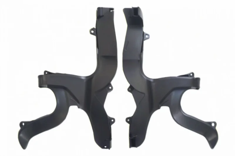
Mold Closing and Inflation
When the parison reaches the predetermined length, the blow mold closes rapidly, sandwiching the parison. A blow rod pierces the center of the parison, injecting high-pressure compressed air (typically 0.5-1.0 MPa). The high-pressure air causes the softened parison to expand rapidly, tightly adhering to the entire mold's inner wall.

Mold Opening and Demolding
Once the product has cooled sufficiently and gained enough rigidity, the mold opens, and the formed hollow component is removed through an ejection mechanism or robotic arm. Proper timing is crucial to prevent deformation while maintaining production efficiency.
Melting and Parison Extrusion
Dried plastic granules are gradually melted and plasticized through the extruder screw's conveying, compression, and mechanical shearing actions. The melt is then precisely extruded under high pressure to form a tubular hollow semi-finished product called a "parison."
Cooling and Solidification
Critical Step: The mold contains precise cooling water channels that rapidly remove heat from the high-temperature plastic through circulating cooling water, causing it to solidify. Cooling speed and uniformity directly affect internal stress, warping, and dimensional stability of the product.
Post-processing
After demolding, products require flash trimming to remove excess plastic from mold seams. For precision components, additional secondary processing may include drilling, welding, assembly, surface printing, or labeling to meet specific application requirements.
Key Technologies and Control Points for HVAC Blow Molding
Material Selection and Performance Matching
Components must maintain stable performance over a wide temperature range (e.g., -30°C to 80°C), resist corrosion from refrigerants and oils, and possess good impact resistance, rigidity, and fatigue resistance.
Airtightness and Structural Strength
In-depth Analysis: This is the lifeline for HVAC duct components. The one-piece hollow structure of blow molding fundamentally eliminates potential leak points found in traditional metal ducts, such as weld seams and flange connections, providing superior airtightness. By optimizing the design, such as adding reinforcing ribs to the inner wall, the component's resistance to collapse and structural rigidity can be significantly increased without adding wall thickness or weight.
Mold Design and Manufacturing Precision
In-depth Analysis: Загрязнения или деградировавший материал приводят к образованию полос на поверхности. Регулярная очистка экструдера и использование фильтрованных материалов могут решить эту проблему.
Typical Applications in the HVAC Field
| Application Component | Blow Molding Advantages | Key Performance Requirements |
|---|---|---|
| Air Conditioning Ducts | Lightweight, one-piece leak-free molding, integrated foam insulation, high design freedom | Airtightness, temperature resistance, low air resistance, chemical resistance |
| Fan Scrolls/Impellers | Precise replication of complex aerodynamic surfaces, good dynamic balance, low cost | Dimensional accuracy, surface finish, structural rigidity, fatigue resistance |
| Accumulators/Receivers | Good pressure resistance, seamless structure, corrosion resistance | Pressure resistance, chemical resistance (refrigerants), sealing |
| Expansion Valve/Valve Bodies | Complex internal cavities molded in one piece, reliable sealing | Precision dimensions, chemical resistance, strength |
| Various Connectors and Guards | Complex shapes, high level of integration, vibration and noise reduction | Flexibility, weather resistance, assembly accuracy |
What are the Common Challenges in HVAC Blow Molding?
HVAC blow molding presents a complex matrix of challenges, requiring specialized knowledge and advanced solutions. From selecting high-performance materials, like moisture-sensitive polymers, to precisely controlling parison extrusion and mold cooling, each stage demands rigorous quality assurance. Common pitfalls include wall thickness variation, warping, surface defects like bubbles and streaks, and structural inconsistencies, often stemming from inconsistent melt flow, mold wear, or poor thermal management. Overcoming these obstacles is crucial for manufacturers to implement effective strategies that minimize defects, optimize production efficiency, and deliver reliable, high-performance HVAC components that meet stringent industry standards.
Key Challenges: Material Performance • Parison Control • Cooling Optimization • Surface Quality • Tooling Precision
Material Selection and Performance Issues
Moisture Sensitivity
Materials like polyamide (PA) absorb moisture, leading to hydrolysis during melting. This causes surface defects (e.g., silver streaks, bubbles) and reduced mechanical properties.
Thermal Degradation
Excessive heating or prolonged residence time in the extruder can degrade polymers, resulting in discoloration, brittleness, or weakened structural integrity.
Inconsistent Melt Flow
Variations in material viscosity due to inadequate mixing or temperature fluctuations affect parison uniformity and final product quality.
Parison Control Defects
Wall Thickness Variation
Non-uniform parison thickness leads to weak spots, uneven cooling, and structural failures. This is often caused by improper die gap settings.
Sagging and Drooping
Heavy parisons may stretch under their own weight, causing thickness disparities and deformation issues.
Length Inconsistencies
Fluctuations in extrusion speed or material supply result in variable parison lengths, disrupting production consistency.
Molding and Cooling Challenges
Incomplete Filling
Insufficient air pressure or delayed mold closing prevents the parison from fully expanding, leading to deformed or incomplete parts.
Cooling-Induced Warping
Uneven mold cooling causes residual stresses, resulting in warping or dimensional inaccuracies. Optimizing cooling channel design is critical.
Cycle Time Inefficiencies
Inadequate cooling prolongs production cycles. Advanced cooling systems or conformal cooling channels can mitigate this.
Surface and Structural Defects
Wrinkles and Folds
Caused by uneven parison extrusion or improper mold closing. Adjusting die gaps or pre-stretching the parison can help.
Bubbles and Voids
Trapped moisture or volatile gases create voids. Thorough material drying and venting improvements are essential.
Streaks and Discoloration
Contaminants or degraded material result in surface streaks. Regular cleaning of the extruder and using filtered materials can resolve this.
Предварительно закаленная сталь
Mold Wear and Misalignment
Prolonged use leads to mold degradation, affecting part accuracy. Regular maintenance and alignment checks are necessary.
Dimensional Instability
Poor mold temperature control or inadequate ejection mechanisms cause part deformation during demolding.
Solutions and Practices
Parison Programming
Use servo-controlled dies to dynamically adjust wall thickness during extrusion, ensuring uniformity.
Simulation Tools
Implement blow molding simulation software (e.g., Moldflow) to predict and optimize wall thickness, cooling, and deformation issues before production.
Material Drying Systems
Integrate desiccant dryers to maintain moisture levels below 0.02% for hygroscopic polymers like PA.
Conformal Cooling
Design molds with cooling channels that follow part geometry to reduce cycle times and warping.
Challenge-Solution Summary Table
| Challenge | Root Cause | Solution |
|---|---|---|
| Wall Thickness Variation | Die gap misalignment | Parison programming + die adjustment |
| Surface Bubbles | Moisture in material | Enhanced drying + venting optimization |
| Warping | Uneven cooling | Conformal cooling channels |
| Cycle Time Delays | Inefficient cooling | Optimized mold design + cooling systems |
| Material Degradation | Excessive heating | Precise temperature control |
What are Simulation Tools for HVAC Blowing Molding?
Advanced HVAC system optimization employs cutting-edge technologies to achieve unparalleled efficiency and comfort. Computational Fluid Dynamics (CFD) precisely simulates airflow and thermal behavior, significantly reducing pressure drops and energy consumption. Topology optimization algorithms generate innovative, lightweight duct designs that maximize performance while minimizing material usage. Furthermore, acoustic simulations identify and mitigate noise sources, ensuring quieter environments. These integrated approaches collectively create HVAC solutions that are quieter, more energy-efficient, and more reliable, setting new standards for performance in modern buildings.
Key Technologies: Computational Fluid Dynamics • Topology Optimization • Acoustic Simulation
CFD Optimization
Computational Fluid Dynamics (CFD) is essential for modern HVAC design, simulating fluid flow, pressure, and thermal behavior to identify issues before prototyping. By selecting appropriate turbulence models like k-ε or k-ω SST, engineers can accurately predict pressure losses and optimize duct geometries.
This process allows for significant reductions in pressure drops—up to 30%—and ensures precise thermal analysis for critical applications like data.
Topology & Shape Optimization
Topology optimization uses algorithms to generate the most efficient material layout within a design space. By integrating with CFD, it automatically creates duct geometries with smoother transitions and optimized cross-sections, reducing turbulence and pressure losses.
This method is crucial for space-constrained applications and promotes lightweighting, cutting material costs and simplifying installation without compromising structural integrity or performance.
Acoustic Performance & Noise Reduction
CFD-based aeroacoustic simulations identify noise sources like vortex shedding, guiding to minimize noise generation.
Helmholtz resonators and expansion chambers are strategically tuned to target and attenuate specific problematic noise frequencies.
Coupled acoustic-structural simulations ensure noise reduction measures do not compromise the duct's durability or airflow performance.
How Long is the Service Life of HVAC Blow Molds?
The service life of a blow mold is not a fixed figure but a wide range, typically from 500,000 to over 1 million cycles. This longevity is primarily determined by the mold material, with aluminum offering shorter lifespans and hardened tool steel providing the greatest durability. Beyond material, factors such as the abrasiveness of the resin used, part geometry, processing parameters, and the rigor of maintenance practices all play a critical role. Ultimately, a mold's lifespan is a measure of ROI, balancing its initial cost against its long-term productivity.
Key Factors: Mold Material • Resin Type • Part Geometry • Maintenance • Temperature Control • Repair Strategies
1. The Single Most Critical Factor: Mold Material
| Material | Life (Cycles) | Best For |
|---|---|---|
| Aluminum | 500k - 1M | Low-to-medium volume |
| Pre-Hardened Steel | Передовые температурные решения | Medium-to-high volume |
| 420 Stainless Steel | 2M - 4M | Corrosive resins (PVC) |
| Hardened Tool Steel | 3M+ | Very high-volume, abrasive resins |
2. Production & Maintenance Factors
Production Factors
- • Resin Type: Abrasive fillers (glass, carbon) drastically reduce life.
- • Part Geometry: Sharp corners create high-stress points.
- • Processing: Excessive pressure, temperature, and long cycle times cause fatigue.
Maintenance & Handling
- • Regular Cleaning: Prevents residue buildup and surface scratches.
- • Proper Polishing: Maintains cavity finish and prevents defects.
- • Storage: Clean, coated, and stored in a dry environment to prevent corrosion.
3. Deep Dive: Resin Type Impact on Mold Life
Abrasive Resins
The abrasiveness of resins varies significantly based on their filler content. For example:
- • Glass Fiber Reinforced Nylon: Extremely abrasive, can reduce mold life by up to 50% compared to unfilled materials.
- • Mineral Filled Polypropylene: Moderately abrasive, typically reduces mold life by 20-30%.
- • Carbon Fiber Composites: Highly abrasive, requires hardened steel molds for extended life.
Corrosive Resins
Certain resins release corrosive gases during processing that attack mold surfaces:
- • PVC (Polyvinyl Chloride): Releases HCl gas during processing, which corrodes standard steel molds.
- • Acetals: Can release formaldehyde, causing corrosion in unprotected molds.
- • Solution: 420 stainless steel or specially coated molds resist corrosion and extend service life.
4. Critical Factor: Mold Temperature Control
Impact of Improper Temperature Control
- • Thermal Fatigue: Uneven temperature distribution causes surface cracking (heat checking).
- • Product Defects: Warping, inconsistent shrinkage, and poor surface finish.
- • Extended Cycle Times: Inefficient cooling increases production time and energy costs.
- • Reduced Mold Life: Thermal stress accelerates wear and tear.
Advanced Temperature Solutions
- • Корпус из алюминия + вставки из бериллиевой бронзы: 3D-printed channels that follow the product contour for uniform cooling.
- • Baffled Cooling Systems: Enhanced water flow design for efficient heat removal.
- • Thermal Pins: Conductive inserts that rapidly transfer heat from critical.
- • Temperature Controllers: Precision systems that maintain optimal mold temperature within ±1°C.
5. Material Selection: The Cost-Performance-Cycle Triangle
Selecting mold materials involves balancing three critical factors. Understanding these trade-offs helps optimize ROI for specific production scenarios:
Cost Considerations
- • Aluminum: Lowest initial cost
- • P20 Steel: Moderate cost
- • Hardened Steel: Highest initial cost
Performance Factors
- • Durability & wear resistance
- • Surface finish quality
- • Resistance to corrosion
Cycle Time Impact
- • Aluminum: Fastest cooling
- • Steel: Slower but more stable
- • Copper alloys: Excellent heat transfer
Example: For medium-volume production (500k-1M parts), aluminum molds might seem cost-effective due to faster cycle times (up to 30% faster cooling), but may require replacement sooner. In contrast, P20 steel molds have higher initial costs but offer longer service life, potentially reducing total cost of ownership over multiple production runs.
6. Extending Economic Life: Mold Repair & Refurbishment
Common Repair Techniques
- • Laser Welding: Precise material addition to damaged areas with minimal heat distortion.
- • EDM Repair: Electrical discharge machining for precise removal of damaged material.
- • Surface Coatings: PVD, nitriding, or chrome plating to restore surface hardness.
- • Cavity Re-machining: Complete restoration of worn surfaces to original specifications.
When to Repair vs. Replace
- • Repair When: Damage is localized, mold base is sound, and repair cost is <50% of new mold.
- • Replace When: Core/cavity is extensively worn, cooling system is damaged, or design changes are needed.
- • ROI Consideration: Calculate repair cost + expected remaining life vs. new mold cost + full lifespan.
- • Production Impact: Factor in downtime during repair vs. longer-term reliability of new mold.
7. Advanced Strategy: Hybrid Mold Construction
Hybrid molds combine different materials in strategic locations to optimize cost, performance, and longevity:
Common Hybrid Configurations
- • P20 Base + H13 Inserts: Cost-effective body with high-wear inserts at critical areas.
- • Aluminum Body + Beryllium Copper Inserts: Обеспокоенность клиента: Сроки проекта, необходимость планирования запуска продукта или завершения проекта.
- • Steel Base + Coated Inserts: Standard construction with specialized coatings for specific resin compatibility.
Strategic Insert Placement
- • Parting Line: High-wear area benefits from hardened steel inserts.
- • Pinch-off Areas: Subject to high stress and wear.
- • Neck Ring: Critical for thread formation and requires precision.
- • High Heat Zones: Copper or beryllium copper inserts improve cooling efficiency.
Cost-Benefit Analysis: Hybrid molds typically cost 20-40% more than standard steel molds but can extend service life by 50-100% while reducing cycle times by 10-20%. For medium to high-volume production, this approach often provides the best ROI by balancing initial investment with long-term productivity.
Frequently Asked Questions About HVAC Blow Molding
Understanding the technical aspects of HVAC blow molding is crucial for project success. This includes grasping typical manufacturing tolerances, strategies for integrating features like mounting points, and inherent design limitations such as minimum wall thickness. Our components are engineered to withstand a wide range of pressure and temperature demands, with standard lead times from 30-50 days. We are also committed to sustainability, prioritizing the use of recyclable materials and supporting environmentally responsible manufacturing practices to meet modern project requirements.
Key Benefits: Design Feasibility • Manufacturing Tolerances • Integrated Features • Performance Ratings • Clear Lead Times • Sustainability
Our Solutions:
Standard Tolerances:
Typically, manufacturing tolerances for blow molded parts are around ±0.5% of the dimension, but this can vary based on part size and geometry.
Critical Dimensions:
For critical mating surfaces or features, we can achieve tighter tolerances (e.g., ±0.25 mm) through precise mold design and process control.
Factors Affecting Tolerance:
Material type (shrink rate), part wall thickness, and mold cooling uniformity are key factors we manage to ensure consistent dimensional accuracy.
Our Solutions:
Post-Molding Operations:
The most common method. Holes, slots, and cutouts are created using CNC machining, drilling, or ultrasonic welding after the initial molding.
In-Mold Features:
For flanges or reinforced areas, the mold cavity can be designed to form these features directly. Mounting points can be molded as thicker, more robust sections.
Internal Baffles:
Created by using a collapsible core pin within the mold or by welding separate internal pieces after molding to form the desired baffle structure.
Our Solutions:
Minimum Wall Thickness:
Generally 1.5mm to 3mm, depending on the material and part size. Thinner walls can lead to inconsistencies and weak spots.
Undercuts & Internal Threads:
True undercuts are not possible in a single-piece blow mold. They require complex, expensive collapsible core mechanisms or must be created in a secondary operation.
Sharp Corners:
Should be avoided. We recommend using generous radii (fillets) on both internal and external corners to ensure material flows evenly and to prevent stress concentrations.
Our Solutions:
Pressure Rating:
Depends heavily on material, wall thickness, and geometry. For air ducts, ratings are often low (e.g., < 5 psi). For fluid reservoirs or plenums, ratings can be much higher (15-50+ psi) with proper design and materials like HDPE or PP.
Temperature Rating:
Determined by the material's heat deflection temperature (HDT). Standard PE is suitable for up to ~60°C (140°F), while PP can handle ~100°C (212°F). For higher temperatures, engineering plastics like Polycarbonate (PC) are used.
Our Solutions:
Оглавление HVAC
Our Solutions:
Widely Recyclable Materials:
Yes, the most common materials we use—such as Polyethylene (PE), Polypropylene (PP), and Polycarbonate (PC)—are thermoplastics and are 100% recyclable.
Recycling Process:
Parts can be collected, shredded, washed, and melted down to create pellets, which are then used to manufacture new plastic products, reducing landfill waste.
Sustainable Options:
We can also incorporate Post-Consumer Recycled (PCR) resins into your parts, further enhancing the sustainability of your project without compromising performance.
Ready to Start Your Extrusion Project?
Partner with HVACore for precision plastic extrusion molding solutions. Our engineering team is ready to optimize your HVAC component designs for manufacturability and performance.