
- フラット面平面度 ±0.3 mm、抗菌オプション.
- Injection molding delivers dimensional repeatability of ±0.1–0.3 mm, making it the dominant process for high-volume HVAC plastic parts.
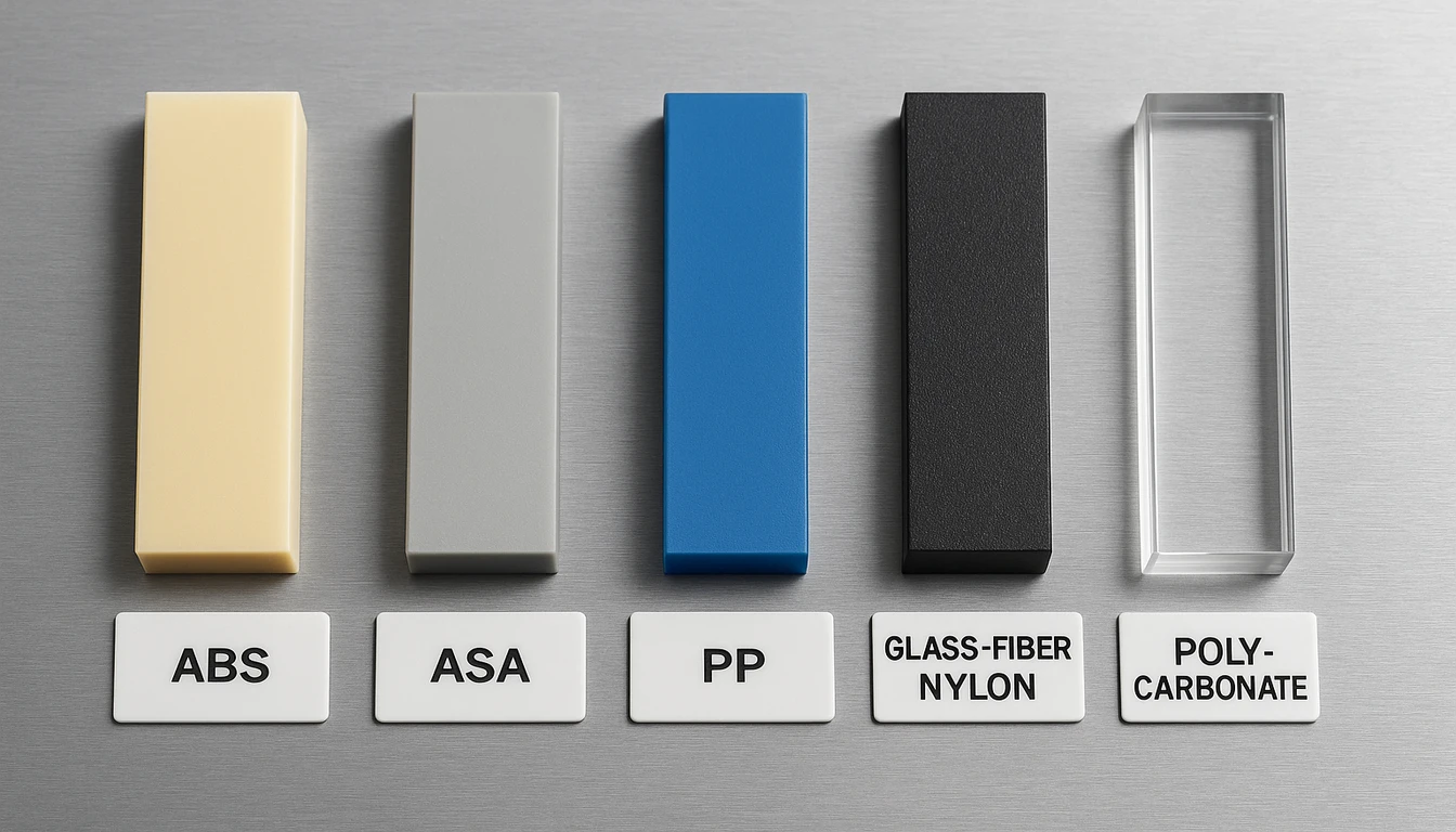
- Material selection—ABS, ASA, PP, glass-filled nylon, or PC—is driven by UV exposure, chemical resistance, and structural load requirements.
- A rigorous DFM review, T1 trial, and in-process statistical process control (SPC) reduce scrap rates to under 0.8% at full production.
- HVACore supports prototyping to 500,000+ parts/year across grilles, duct fittings, filter frames, dampers, and enclosures.
What Makes Custom HVAC Plastic Components Different from Standard Parts?
Custom HVAC plastic components1 must endure −40 °C to +120 °C and hold ±0.2 mm tolerances across 10,000+ thermal cycles. Custom HVAC plastic components must meet a far stricter set of performance requirements than general-purpose plastic parts: continuous heat resistance above 85 °C, dimensional stability across wide temperature swings, low volatile organic compound (VOC) outgassing, and flammability compliance to UL 94 V-0 or V-2. A standard off-the-shelf plastic part is designed to a generic specification; a custom HVAC component is designed around the exact airflow path, mounting interface, and operating environment of a specific unit.
| HVAC Operating Challenge | Standard Part Limitation | Custom Component Advantage |
|---|---|---|
| −40 °C to +120 °C thermal cycling | Warping after ~1,000 cycles | Stable to ±0.2 mm across 10,000+ cycles |
| UL 94 V-0 flammability requirement | Generic ABS: HB rating only | Flame-retardant resin selected per certification |
| IAQ / VOC compliance | Unverified outgassing levels | Low-VOC formulations tested per ASHRAE 62.1 |
The thermal cycling in a typical split-system air conditioner can push duct fittings from −10 °C on a cold start to +80 °C at the heat exchanger face within minutes. That same fitting must snap into a tight channel tolerance of ±0.2 mm to maintain the sealing bead. Off-the-shelf parts simply cannot hold those tolerances across 10,000+ thermal cycles without a tailored material and mold design.
“HVAC plastic components require UL 94 flammability certification for use in air-handling units.”True
North American and European HVAC equipment standards mandate that plastic parts in air-handling paths carry UL 94 V-0 or V-2 ratings. Flame-spread inside ductwork is a life-safety issue, so certification is not optional—it is a prerequisite for product approval.
“Any generic ABS part can be substituted for a custom HVAC plastic component.”False
Generic ABS typically rates HB on UL 94—the least stringent flammability class—and begins to soften above 80 °C. Custom HVAC applications routinely require V-0 rated, heat-stabilized grades with tight pigment and additive packages specified for the exact operating environment.
Additional differentiators include: antimicrobial additive packages for filter housings in healthcare HVAC, UV-stabilized resins for outdoor condenser covers, and glass-fiber reinforcement in structural brackets that bear compressor vibration loads. Each requirement eliminates generic substitutes and mandates a purpose-engineered component.
Which HVAC Components Are Injection Molded?
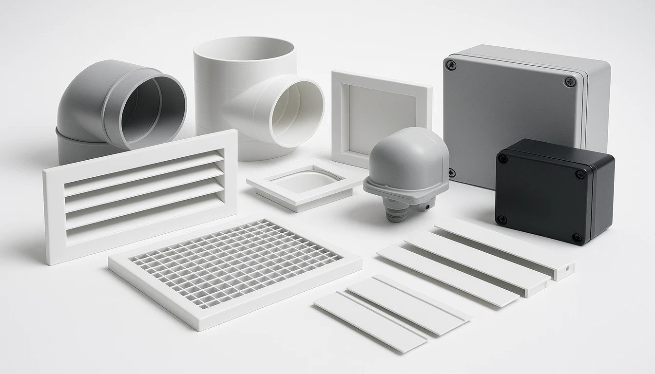
Eight component families are injection-molded in HVAC: grilles, dampers, duct fittings, filter frames, sensor housings, brackets, seals, enclosures. injection molding2 is the process of choice for the vast majority of custom HVAC plastic parts because it combines high dimensional accuracy with fast cycle times at volumes above a few thousand pieces per year. The eight component families produced by injection molding cover nearly every plastic part in a modern HVAC system.
| Component | Typical Material | Key Requirement | Annual Volume Range |
|---|---|---|---|
| Air vent grilles & registers | ABS / ASA | UV stability, snap-fit tolerance ±0.15 mm | 50,000–500,000+ |
| Damper blades & housings | Glass-nylon (PA6-GF30) | Dimensional stability, low creep | 20,000–200,000 |
| Duct fittings & elbows | PP / ABS | Sealing bead geometry, pressure drop <5 Pa | 30,000–300,000 |
| Filter frames & covers | ABS / PP | Flat face planarity ±0.3 mm, antimicrobial option | 1.8× |
| Sensor housings | PC / ABS alloy | EMI shielding capability, heat resistance 100 °C | 5,000–80,000 |
| Mounting brackets | PA6-GF30 | Tensile strength >80 MPa, vibration fatigue life | 10,000–200,000 |
| Seals & flexible connectors | TPE / TPV | Compression set <25%, −40 °C to +120 °C | 20,000–250,000 |
| electrical enclosures | PC / ABS (V-0) | UL 94 V-0, IP54+ gasket groove tolerance | 5,000–100,000 |
For air vents and grilles, the visible surface quality demand adds a cosmetic dimension: Class A surfaces free of sink marks, weld lines, and silver streaks. For electrical enclosures3, the mold must produce a gasket seat groove accurate to ±0.1 mm to guarantee IP-rated sealing without post-machining. This combination of functional, structural, and cosmetic requirements is why custom tooling—rather than commodity components—is specified by OEMs.
Flexible components such as seal collars and accordion-style duct connectors are produced via injection molding of thermoplastic elastomers (TPE or TPV), sometimes over-molded onto a rigid PP substrate to create a two-material assembly in a single production step. This eliminates a secondary bonding operation and reduces leak risk.
| Material | Typical HDT (°C @ 1.8 MPa) | Primary HVAC Use Case |
|---|---|---|
| ABS | 88–100 °C | Grilles, covers, filter frames |
| PA6-GF30 | 200–210 °C | Load-bearing brackets, structural housings |
| PP | 90–110 °C | Duct connectors, moisture-exposed fittings |
How Do We Select the Right Material for Each Component?
HVAC plastic material selection is driven by HDT (°C), UL 94 rating, UV stability, chemical resistance, IAQ compliance, and cost. Material selection is the single highest-leverage decision in custom HVAC plastic component engineering: the wrong resin can cause field failures within 12 months, while the right one delivers 15+ years of reliable service. Our engineers evaluate five material families against seven performance criteria before finalizing a specification.
The seven criteria evaluated for every HVAC plastic component are: (1) heat deflection temperature at the expected worst-case operating temperature plus a 15 °C safety margin; (2) UL 94 flammability rating required by the end-product certification; (3) UV resistance class for outdoor or near-window installations; (4) chemical resistance to refrigerants, lubricants, and cleaning agents; (5) dimensional stability (low moisture absorption and low coefficient of thermal expansion); (6) regulatory compliance for indoor air quality; and (7) cost per kilogram against the target component unit economics. No single material scores best on all seven, making selection an engineering trade-off rather than a default choice.
| Material | HDT (°C, 1.8 MPa) | UV Resistance | Flame Rating | Strength (MPa) | Cost Index | Typical HVAC Use |
|---|---|---|---|---|---|---|
| ABS | 85–100 | Poor (needs additive) | HB / V-0 grades | 40–55 | 1.0× | Interior grilles, covers, filter frames |
| ASA | 85–100 | Excellent | HB / V-0 grades | 40–50 | 1.3× | Outdoor condenser covers, exterior vents |
| PP (homo/co) | 90–110 | Fair (needs UV pkg) | HB / V-2 grades | 25–40 | 0.8× | Duct fittings, drain pans, flex connectors |
| PA6-GF30 | 200–210 | Poor | HB / V-2 grades | 120–160 | 1.8× | 受入基準 |
| PC / ABS alloy | 100–120 | Fair | V-0 grades available | 50–65 | 1.6× | Enclosures, sensor housings, thin-wall covers |
| TPE / TPV | 60–80 (flex) | Good | V-0 grades available | 8–20 | 2.0× | Seals, gaskets, flex connectors, grommets |
For seals and flexible hoses, the compression set after 1,000 hours at 70 °C is the decisive metric—grades with >30% set allow air bypass that degrades system efficiency. For outdoor components in tropical climates, ASA outperforms standard ABS on delta-E color shift after 1,000 hours of accelerated weathering (ASTM G154): ASA typically shows 8 for unmodified ABS.
“Glass-filled nylon (PA6-GF30) is the preferred material for load-bearing HVAC brackets due to its high heat deflection temperature.”True
PA6-GF30 offers an HDT of 200–210 °C at 1.8 MPa—more than double standard ABS—and tensile strength of 120–160 MPa. In fan-motor bracket applications subjected to continuous vibration, its fatigue resistance outlasts unreinforced thermoplastics by a factor of 3–5× in standardized testing.
“Polypropylene is suitable for all HVAC plastic components because it resists moisture well.”False
PP’s moisture resistance is excellent, but its low HDT (90–110 °C at 1.8 MPa) and poor UV stability make it unsuitable for high-temperature zones near heat exchangers or outdoor applications without extensive additive packages. PP also struggles to achieve UL 94 V-0 without flame retardant loading, which can reduce impact strength.
What Does the Custom HVAC Plastic Manufacturing Process Look Like?
Custom HVAC plastic manufacturing is a four-stage process: DFM review, mold build, T1 trial, and mass production. Custom HVAC plastic component manufacturing follows a disciplined four-stage process: DFM review, mold development, T1 trial, and validated mass production. Skipping or compressing any stage multiplies downstream cost—a mold modification at T2 typically costs 3–8× what the same change would have cost at the DFM stage.
Unlike commodity injection molding, HVAC plastic parts often combine multiple functional requirements in a single component—a filter frame must be dimensionally flat, structurally rigid enough to resist airflow pressure, and chemically compatible with the cleaning agents used during HVAC maintenance. This multi-requirement profile drives the need for a thorough design and process development sequence rather than a simple quote-and-ship approach.
| Manufacturing Stage | Key Deliverable | Typical Timeline |
|---|---|---|
| Stage 1: DFM Review | Redlined PDF: wall thickness, draft angles, gate feasibility | 5 business days |
| Stage 2: Mold Development | Production-grade tool in P20 or H13 steel | 4–6 weeks |
Stage 1 — DFM Review and Mold Flow Analysis
Every custom HVAC plastic component begins with a DFM review of the 3D CAD model. Our engineers check wall thickness uniformity (target 2.0–3.5 mm for most HVAC parts), draft angles (minimum 1° per side for textured surfaces, 0.5° for polished), rib-to-wall thickness ratios (≤60% to avoid sink marks), and gate feasibility. A mold flow simulation then predicts fill pattern, weld line locations, air trap positions, and warpage under the target processing window. Parts with predicted warpage >0.5 mm/100 mm are redesigned before steel is cut.
The DFM report is delivered as a redlined PDF within 5 business days. For complex assemblies—such as a multi-part ductwork manifold with six snap-fit interfaces—the DFM review also covers assembly stack-up tolerance to confirm the ±0.3 mm system-level fit requirement before individual component tolerances are allocated.
| DFM Check Item | Target Specification | Risk if Out-of-Spec |
|---|---|---|
| Wall thickness uniformity | 2.0–3.5 mm for most HVAC parts | Sink marks, warpage, extended cycle time |
| Draft angle (textured surface) | Minimum 1° per side | Part sticking in mold, surface drag marks |
| Rib-to-wall thickness ratio | ≤ 60% | Sink marks on rib base |
Stage 2 — Mold Development and Steel Selection
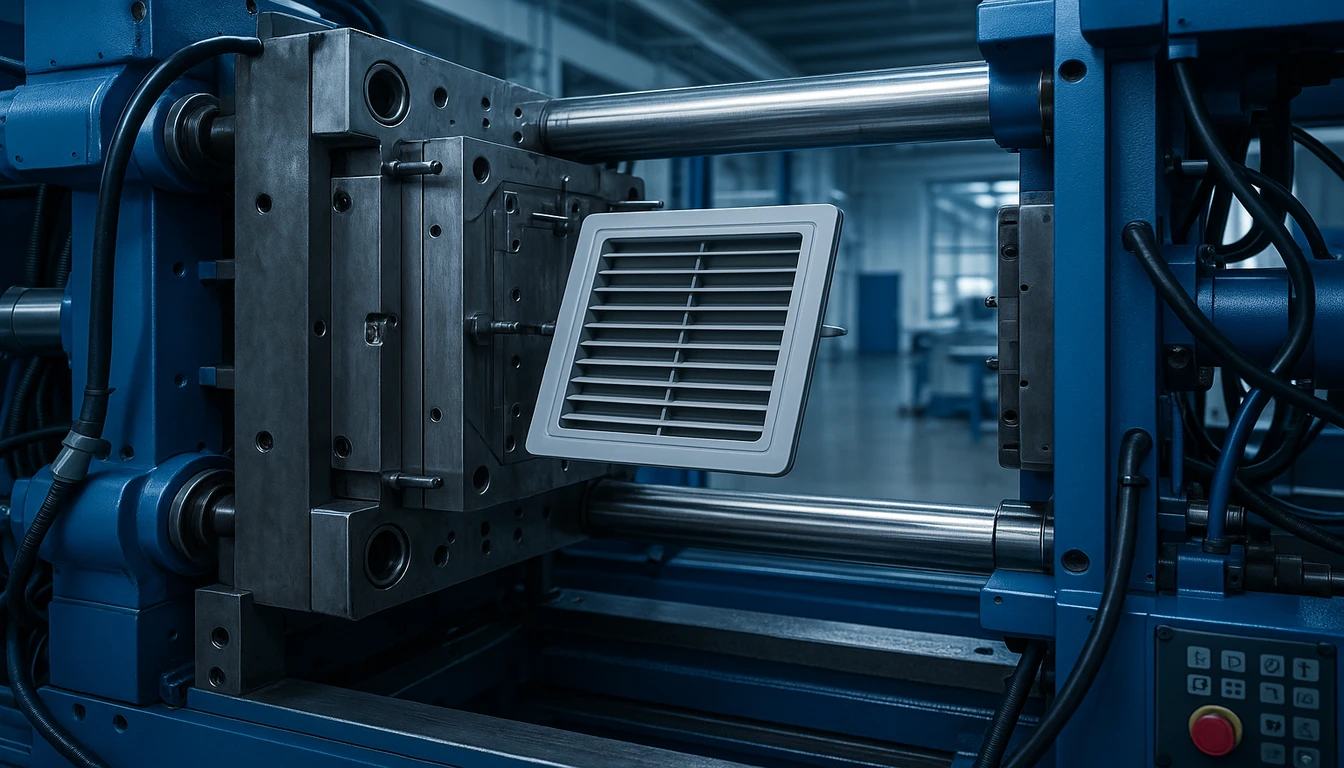
For HVAC mold development, tool steel selection depends on expected production volume and resin abrasiveness. Standard HVAC molds for ABS/PP run in P20 pre-hardened steel (HRC 28–32) and deliver 500,000+ shots. Glass-filled nylon applications require H13 hardened steel (HRC 48–52) to resist abrasion from the glass fibers. Cavity surface finish is CNC-milled to Ra 0.8 µm, then hand-polished to Ra 0.2 µm for Class A surfaces on visible grille faces.
Cooling system design—channel diameter, pitch, and proximity to the cavity wall—is engineered to achieve a mold surface temperature variation of less than ±3 °C across the cavity. Uniform cooling directly governs dimensional consistency and cycle time. A poorly cooled mold can add 30–40% to cycle time and produce warped parts that fail flatness specifications.
Stage 3 — T1 Trial and Process Optimization
The T1 trial produces the first parts from the production tool. Our team runs a Design of Experiments (DoE) study across injection speed, pack pressure, melt temperature, and cooling time to define the robust processing window. T1 parts are measured against the full inspection plan—typically 20–40 dimensions using CMM (coordinate measuring machine) and optical comparator—before any process optimization begins.
T1 approval requires all critical dimensions within specification at Cpk ≥1.33, surface appearance free of Class 1 defects (shorts, burns, delamination), and mechanical property verification (e.g., snap-fit insertion force 15–25 N for a standard grille clip). Most HVAC plastic components reach T1 approval in one or two trials; complex multi-cavity molds with tight tolerances may require a T2.
Weld Lines and Shrinkage Compensation
A critical part of T1 analysis for HVAC plastic parts is weld-line evaluation. Where two flow fronts meet in a mold—common in grilles with multiple ribs or enclosures with through-holes—a weld line forms. Weld-line tensile strength is typically 60–80% of the virgin resin strength. For structural brackets and enclosure walls, weld-line locations must be confirmed by the mold flow simulation and verified by cross-section tensile testing of T1 samples. Gate relocation or process adjustment during T1 can move weld lines away from high-stress zones.
| T1 Evaluation Item | Acceptance Criterion | フィルターフレームとカバー |
|---|---|---|
| Critical dimensions (CMM) | All within spec at Cpk ≥ 1.33 | Process DoE adjustment or T2 trial |
| Surface appearance | No Class 1 defects (shorts, burns, delamination) | Gate or venting modification |
Shrinkage compensation is another T1 focus. Each thermoplastic resin shrinks at a characteristic rate (PP: 1.0–2.5%, ABS: 0.4–0.8%, PA6-GF30: 0.3–0.8% flow direction) as it cools. The mold cavity is intentionally cut larger than the nominal part dimension by the predicted shrinkage factor. If actual shrinkage at T1 differs from the predicted value—due to actual processing conditions, colorant loading, or regrind content—steel dimensions are adjusted by selective welding or EDM re-cutting. Shrinkage variation is the most common root cause of dimensional non-conformance at T1 for new HVAC plastic component programs.
| Resin | Typical Shrinkage Rate | Dimensional Risk Level |
|---|---|---|
| PP (Polypropylene) | 1.0–2.5% | High — requires careful cavity compensation |
| ABS | 0.4–0.8% | Medium — predictable with standard DoE |
| PA6-GF30 | 0.3–0.8% (flow direction) | Medium — anisotropic, needs flow simulation |
Stage 4 — Mass Production and SPC Monitoring
Validated production runs include in-process SPC on critical dimensions, automated vision inspection for cosmetic defects, and material lot traceability. Our factory’s production cells run 24 hours, 5 days per week, with an OEE (Overall Equipment Effectiveness) target of 82%. Reject rates at full-rate production average under 0.8% for standard HVAC plastic components.
How Do We Ensure Quality in Custom HVAC Plastic Parts?
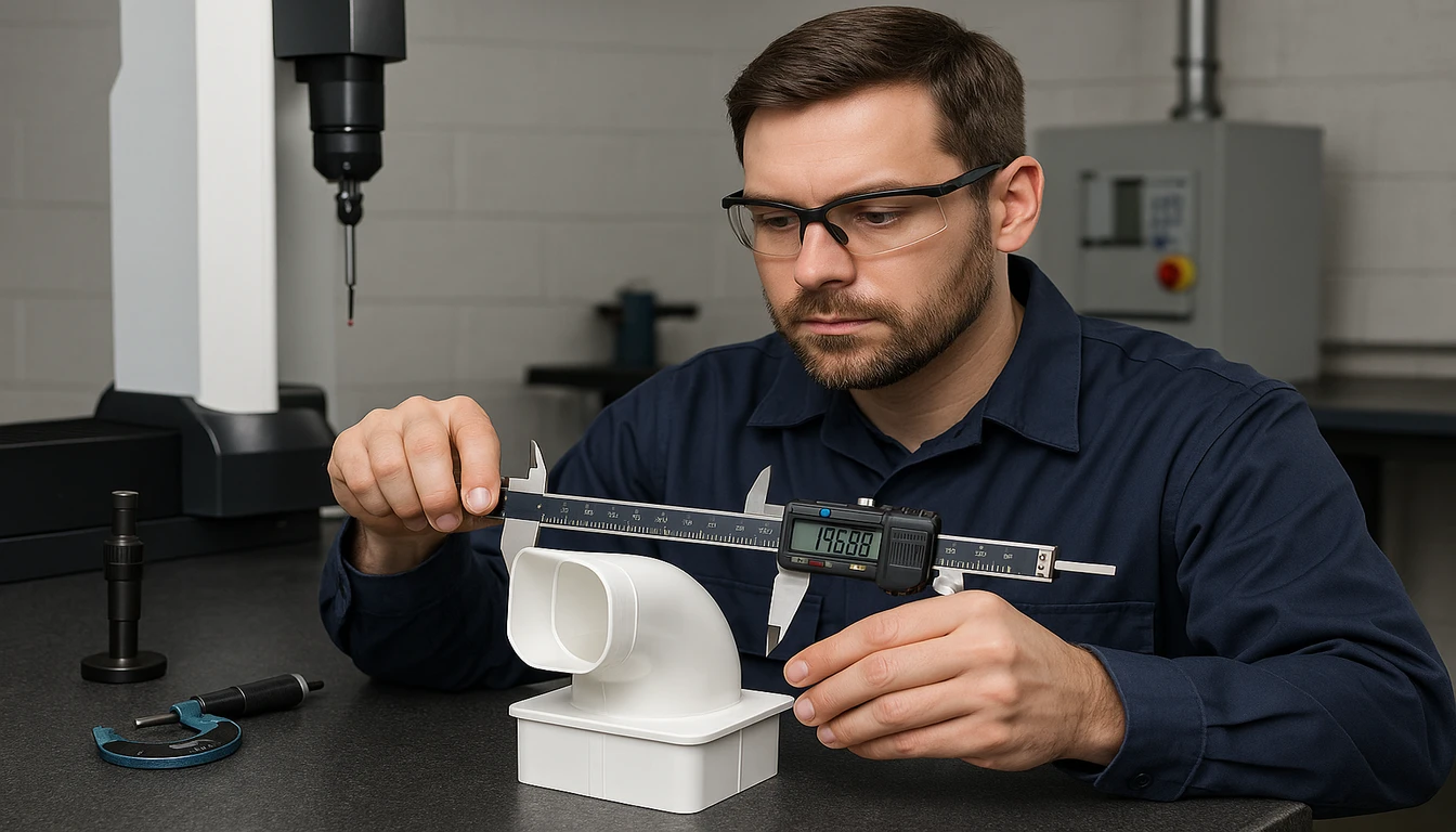
HVAC plastic part quality is verified by CMM inspection to ±0.1 mm and UL 94 flammability tests per material lot. Quality assurance for custom HVAC plastic parts spans incoming material verification, in-process dimensional control, functional testing, and finished-goods audit. HVACore operates under ISO 9001:2015 and follows PPAP (Production Part Approval Process) documentation requirements for OEM customers who specify automotive-level rigor.
| Test | Method / Standard | Acceptance Criterion | Frequency |
|---|---|---|---|
| Dimensional CMM inspection | ISO 10360 | Cpk ≥ 1.33 on critical dims | First 5 shots + every 500 shots |
| Flammability (UL 94) | UL 94 V-test | V-0 or V-2 per drawing requirement | Per material lot change |
| Heat deflection temperature | ISO 75 / ASTM D648 | ≥ HDT specified on material datasheet | Incoming material audit |
| Snap-fit insertion/retention force | Custom fixture | 15–25 N insert, ≥ 40 N retention | First article + 1% sample |
| UV weathering (outdoor parts) | ASTM G154 (1000 hrs) | Delta-E < 3, no surface cracking | Qualification only |
| Pressure drop (duct fittings) | ASHRAE 120 | Within ±8% of design specification | First article |
| IP-seal gasket groove check | Go/No-Go gauges | Zero rejections at CMM check | 100% for enclosures |
For filter frames and covers, カスタムHVACプラスチック部品:材料、プロセス、品質.
Traceability is maintained via a data matrix code molded into each part cavity. The code encodes production date, shift, cavity number, and material lot, enabling full genealogy trace within 2 hours in the event of a field quality concern. This level of traceability is increasingly required by commercial HVAC OEMs as part of their supplier qualification.
Frequently Asked Questions?
What is the minimum order quantity for custom HVAC plastic components?
We support custom HVAC plastic components from as low as 500 pieces for prototyping and low-volume production runs. For standard injection-molded parts in a single-cavity tool, the economic crossover point versus CNC machining typically occurs around 1,000–2,000 pieces per year. Multi-cavity molds become cost-effective above 50,000 pieces per year. HVACore can quote single-cavity, family, and multi-cavity tooling configurations to match your volume and budget. We also offer rapid-prototyped samples in production-equivalent materials before committing to full tooling investment. Contact us for a no-obligation quote with DFM feedback.
How long does it take to develop a custom HVAC plastic mold?
Standard HVAC plastic mold development takes 4–6 weeks from approved 3D CAD to T1 samples. Complex multi-cavity molds or parts with tight tolerances (±0.05 mm) may require 7–10 weeks. The DFM review and mold flow simulation are completed in the first 5 business days; steel procurement, CNC machining of the cavity and core, and EDM finishing comprise the remaining lead time. Expedited tooling in 3 weeks is available at additional cost for critical-path projects. Production lead time after T1 approval is typically 3–5 business days for standing orders.
Which plastic materials comply with HVAC indoor air quality (IAQ) requirements?
For indoor air quality compliance in HVAC applications, materials should meet low-VOC emission standards such as California CDPH 01350 for plenum and air-handler components and GREENGUARD Gold. ABS and PC/ABS alloys from major resin suppliers including BASF, Covestro, and LG Chem are available in certified low-emission grades. PP is naturally low in VOC and widely used for drain pans and ductwork. We source and qualify specific certified resin grades and provide full material documentation, safety data sheets, and emission test reports for OEM compliance submissions.
Can custom HVAC plastic components be produced with antimicrobial properties?
Yes. Antimicrobial additives—typically silver-ion-based masterbatches compounded into ABS, PP, or PC/ABS—are available for filter frames, drain pans, and indoor unit covers used in healthcare, food service, and residential HVAC applications. The additive provides persistent antimicrobial activity tested to ISO 22196, typically achieving 99% or greater reduction of Staphylococcus aureus and E. coli after 24 hours of contact. The additive does not significantly affect mechanical properties or UL 94 ratings when properly compounded at 1–3% loading. We provide antimicrobial certification documentation for OEM submissions.
What tolerances can HVACore hold on injection-molded HVAC plastic parts?
HVACore’s standard production tolerances for injection-molded HVAC plastic components are ±0.2 mm on non-critical dimensions and ±0.1 mm on critical fit and seal dimensions. For specialized applications—such as enclosure gasket grooves or precision sensor mounts—tolerances of ±0.05 mm are achievable in hardened steel tooling with in-process CMM verification and temperature-controlled production cells. Wall thickness uniformity is typically held to ±0.15 mm. All critical tolerances are validated at Cpk ≥1.33 during PPAP before volume production begins, with ongoing SPC monitoring throughout the production run.
-
HVAC plastic components: HVAC plastic components refers to injection-molded or thermoformed parts manufactured from engineering thermoplastics that form the structural, airflow-control, and protective elements of heating, ventilation, and air conditioning systems. ↩
-
injection molding: Injection molding is a manufacturing process in which molten plastic is injected under high pressure into a precision steel mold cavity, then cooled and ejected as a finished part. ↩
-
electrical enclosures: Electrical enclosures refers to protective plastic or metal housings designed to shield electrical components, circuit boards, and wiring within HVAC systems from moisture, dust, and mechanical damage, typically rated to IP54 or higher. ↩