- Materiaalkeuze bepaalt of een spuitgegoten HVAC-kleppendecennium twintig jaar cycli in een luchtbehandelingskast overleeft of binnen drie seizoenen bezwijkt. De vijf meest gespecificeerde thermoplasten voor kleppentoepassingen zijn ABS, acetaal (POM), glasgevuld nylon (PA6-GF30), polypropyleen (PP) en polycarbonaat-ABS-legering (PC/ABS), elk gekozen voor een specifieke combinatie van stijfheid, temperatuurbereik en chemische bestendigheid.
- Thermoplastic materials like ABS, POM, and glass-filled nylon outperform metal damper parts in corrosion resistance and weight reduction of 40-60%.
- Properly designed injection-molded damper components achieve airtight leakage rates below 1% at 500 Pa differential pressure.
- Cycle times for a standard damper blade range from 15 to 35 seconds per part, enabling high-volume production.
- Gate location and cooling channel design are the two most critical factors in dimensional stability of damper assemblies.
What Makes Injection Molding the Preferred Process for HVAC Damper Parts?
injection molding1 dominates Strategisch geplaatste ventilatieopeningen en perforaties zorgen voor voldoende luchtstroom terwijl ze bescherming bieden tegen vuil en grote deeltjes.2 damper component manufacturing because it delivers repeatable dimensional accuracy within ±0.05 mm across millions of production cycles. Modern HVAC systems require damper blades, frame channels, pivot pins, and actuator housings that fit together precisely—tolerances that sheet metal stamping and extrusion simply cannot match at equivalent cost. The process also enables complex geometries, including integrated seal grooves, ribbed stiffening structures, and snap-fit retention features, all in a single shot without secondary machining.
| Factor | Injection Molding Advantage |
|---|---|
| Dimensional accuracy | ±0.05 mm — ensures airtight seal contact |
| Per-unit cost (50k+ parts) | Under $0.20 for standard ABS blades |
| Complex geometry | Seal grooves, ribs, snap-fits in single shot |
| Production speed | 1,500–3,500 parts/hour in multi-cavity molds |
The economics are equally compelling. A well-designed injection mold for a standard rectangular damper blade typically amortizes its tooling cost within 50,000 to 80,000 parts, after which per-unit cost drops to under $0.20 for most ABS or polypropylene components. When HVAC manufacturers compare this to aluminum die casting (5–8× heavier tooling investment) or roll-formed steel (requiring separate assembly and finishing steps), injection molding consistently delivers the lowest total cost of ownership over a five-year production run.
Beyond cost, injection molding offers design flexibility that directly translates into better HVAC system performance. Engineers can specify wall thicknesses between 1.5 mm and 4.0 mm for different zones of the same damper blade—thicker at the pivot axis for strength, thinner at the tip to reduce flutter and noise. Integrated living hinges, overmolded seals, and co-injection structures are all achievable, enabling damper assemblies that actively contribute to system efficiency rather than serving as passive flow restrictors.
| Method | Tolerance (mm) | Cycle Time (s) | Min Volume (units) | Best For |
|---|---|---|---|---|
| Injection Molding | ±0.05 | 15–35 | 10,000+ | High-volume precision blades |
| Aluminum Die Casting | ±0.15 | 45–90 | 20,000+ | Heavy-duty structural frames |
| Sheet Metal Stamping | ±0.20 | 5–15 | 5,000+ | Simple flat components |
| CNC Machining | ±0.01 | 120–600 | 1–100 | Prototypes, complex shapes |
| Thermoforming | ±0.30 | 60–120 | 500+ | Large thin-wall panels |
Which Thermoplastics Are Used in HVAC Damper Injection Molding?
Material selection determines whether an injection-molded HVAC damper component survives 20 years of cycling in an air handler or fails within three seasons. The five most specified thermoplastics for damper applications are ABS, acetal (POM), glass-filled nylon (PA6-GF30), polypropylene (PP), and polycarbonate-ABS alloy (PC/ABS), each chosen for a specific combination of stiffness, temperature range, and chemical resistance.
| Material | Tensile Strength (MPa) | Max Temp (°C) | Key Advantage | Common Application |
|---|---|---|---|---|
| ABS | 40–50 | 80 | Low cost, easy processing | Residential damper blades |
| POM (Acetal) | 60–70 | 100 | Low friction, dimensional stability | Pivot bushings, gear actuators |
| PA6-GF30 (Nylon) | 130–160 | 130 | High stiffness-to-weight ratio | Commercial VAV damper frames |
| Polypropylene | 25–35 | 100 | Chemical resistance, light weight | Kitchen exhaust dampers |
| PC/ABS | 50–60 | 110 | Impact resistance, smoke rating | Fire-rated damper assemblies |
ABS dominates residential HVAC applications because its melt flow index of 10–25 g/10 min allows injection of thin-walled blades at relatively low pressures (600–900 bar), reducing clamp tonnage requirements and energy consumption per part. POM (polyoxymethylene acetal) is the material of choice for actuator gears and pivot bearings within the HVAC damper assembly, because its coefficient of friction (0.1–0.3 against steel) translates into smoother actuator travel and longer bearing life without lubrication.
| Material | Melt Temp (°C) | Mold Temp (°C) | Drying Required | Key Processing Note |
|---|---|---|---|---|
| ABS | 220–250 | 40–70 | 80°C, 2–4 hrs | Low moisture sensitivity |
| POM (Acetal) | 190–220 | 60–90 | Optional | Keep melt time short, avoid degradation |
| PA6-GF30 | 240–280 | 80–90 | 80°C, 4–8 hrs (<0.2%) | Must dry; hygroscopic resin |
| PP | 200–250 | 20–50 | Not required | Long flow path possible with low viscosity |
| PC/ABS | 230–280 | 60–90 | 80°C, 2–4 hrs | Good thermal stability, watch shear heat |
Glass-filled nylon (PA6-GF30) has gained significant market share in commercial HVAC damper blades because its 30% short glass fiber content raises tensile strength to 130–160 MPa—nearly three times that of unreinforced ABS—while adding only 15% to material cost. This allows commercial damper blades to span duct widths of 1,200 mm or more without center supports, simplifying installation and reducing pressure drop. The key processing consideration is that PA6-GF30 is hygroscopic and must be dried to under 0.2% moisture content before injection molding to prevent splay and void formation.
How Does Mold Design Affect HVAC Damper Part Quality?
The single most important mold design decision for HVAC damper blades is gate location. For a standard rectangular damper blade (300 mm × 150 mm × 3 mm), a center-edge gate produces symmetric flow that fills both blade halves simultaneously, minimizing weld line formation. Weld lines in damper blades are structural liabilities—they reduce tensile strength by 20–40% at the weld location, creating preferred failure points under repeated airflow3-driven flexing cycles. Simulation using injection molding analysis software before cutting steel identifies and resolves weld line placement before any tooling investment is made.
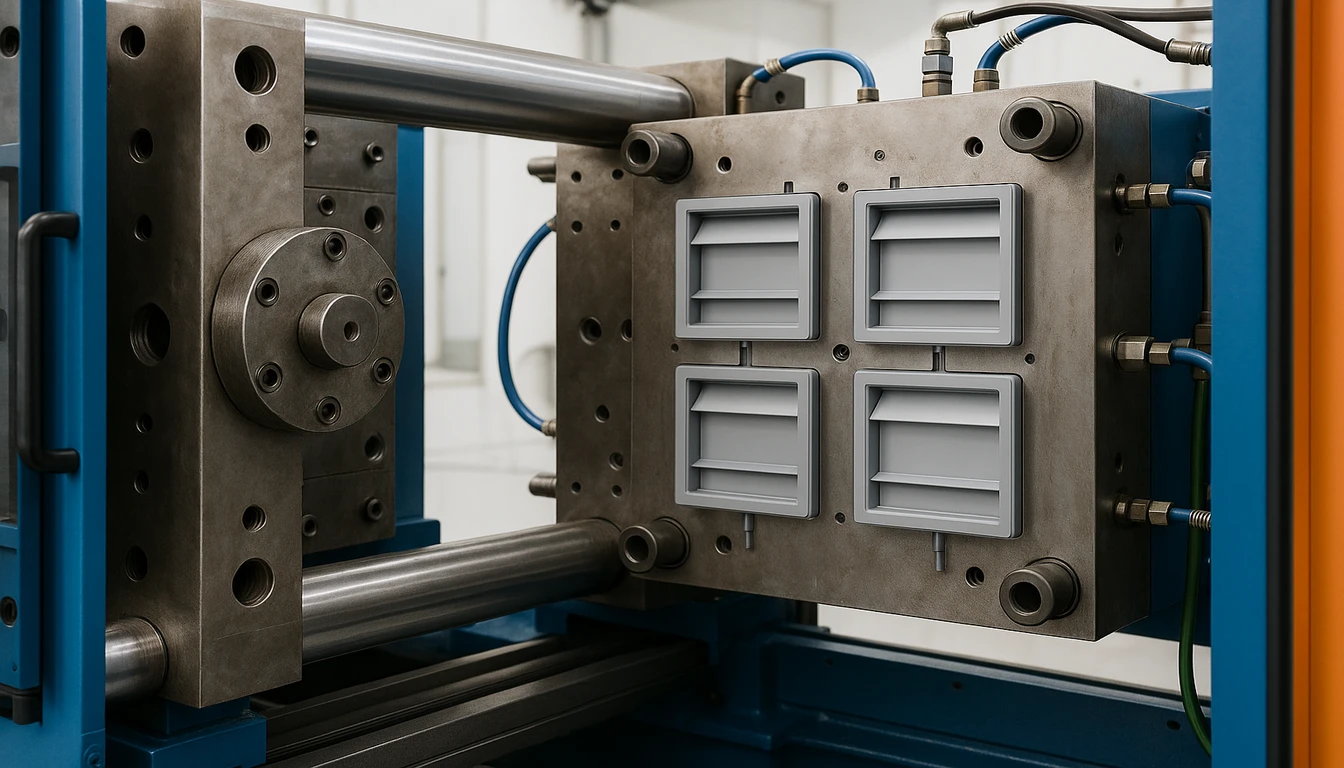
Cooling channel design is the second critical factor. HVAC damper blades have flat, thin-walled geometry that requires balanced cooling from both cavity and core sides to prevent warpage. A temperature differential greater than 5°C between the two mold halves produces bow warpage of 0.3–0.8 mm across a 300 mm blade, which is sufficient to break the airtight seal against the frame gasket and cause leakage rates exceeding 5% at operating pressure. Modern conformal cooling circuits—milled directly into the mold steel following the blade profile—reduce cooling cycle time by 20–30% compared to straight-drilled channels and maintain surface temperature uniformity within ±2°C.
| Abrasief gevulde harsen | Temp Uniformity | Cycle Time | Warpage Risk | Cost |
|---|---|---|---|---|
| Straight drilled | ±8°C | Baseline | Moderate (0.5–0.8 mm bow) | Low |
| Baffle-assisted | ±5°C | -10% | Low (0.3–0.5 mm bow) | Medium |
| Conformal milled | ±2°C | -20 to -30% | Minimal (<0.2 mm bow) | High |
Draft angle is the third critical parameter. HVAC damper blades require a minimum 1.0° draft on all vertical surfaces to ensure clean ejection without cosmetic drag marks. For blades with integrated seal grooves or stiffening ribs, draft angles of 1.5–2.0° are needed to prevent the part from sticking in the cavity during ejection. Insufficient draft is the leading cause of surface defects in damper blades—a problem that cannot be corrected after the mold is built without costly steel rework. Design for manufacturability (DFM) reviews should specifically audit draft angles in the early stages of damper component design.
| Design Parameter | Recommended Value | Consequence if Wrong |
|---|---|---|
| Gate location | Center-edge, single gate | Weld line at blade center, 20–40% strength loss |
| Draft angle (side walls) | 1.0–2.0° | Surface drag marks, part sticking in cavity |
| Cooling temperature differential | <5°C (cavity vs. core) | Bow warpage 0.3–0.8 mm, leakage >5% |
| Wall thickness variation | <3:1 ratio | Differential shrinkage, sink marks on blade face |
Ejector pin placement also deserves attention for HVAC damper applications. Pins must be located in areas that will be hidden in the final assembly—typically along the pivot-axis edge rather than the visible face—and must be sized to distribute ejection force evenly without dimpling or cracking thin-walled sections. For ABS damper blades with wall thickness under 2.0 mm, stripper plate ejection is often preferred over pins, providing full-perimeter support during demold and eliminating witness marks on the cosmetic face of the blade.
| Steel Grade | Hardness (HRC) | Mold Life (shots) | Best Material | Cost Factor |
|---|---|---|---|---|
| P20 | 28–32 | 500,000–1,000,000 | ABS, PP, POM | 1× |
| H13 | 48–52 | 300,000–500,000 | PA6-GF30, PC/ABS | 2.5× |
| S7 | 54–58 | 200,000–400,000 | Abrasive filled resins | 300×150 (woon) |
| 420SS | 50–52 | 400,000–800,000 | Corrosive materials | 3.5× |
“Injection-molded HVAC damper blades achieve leakage rates below 1% at 500 Pa differential pressure when produced with dimensional tolerances under 0.1 mm.”True
Precision injection molding consistently holds tolerances of ±0.05 mm on damper blade width and thickness, ensuring proper seal contact with frame gaskets. Independent testing per AMCA Standard 500-D confirms that well-molded plastic damper assemblies achieve Class I leakage performance (below 4 CFM/ft² at 1 in. w.g.).
“Metal damper components are always stronger than injection-molded plastic parts for HVAC applications.”False
Glass-filled nylon (PA6-GF30) injection-molded components achieve tensile strengths of 130–160 MPa, comparable to many aluminum alloys used in damper construction. Combined with 40–60% weight reduction and inherent corrosion resistance, engineered thermoplastics outperform metals in a wide range of HVAC damper applications, particularly in high-humidity environments like fresh air intakes and exhaust dampers.
What Are the Key HVAC Damper Components Made by Injection Molding?
Modern HVAC damper assemblies consist of eight to twelve individual injection-molded components, each serving a specific structural or sealing function. Understanding which parts are produced by injection molding versus other processes helps HVAC engineers optimize both cost and performance when specifying damper systems. The major injection-molded components in a typical motorized HVAC damper assembly include the blade, blade frame channel, pivot bushing, actuator housing, position indicator cover, end seal retainer, and junction box enclosure.
The damper blade itself is the highest-volume injection-molded component in an HVAC assembly. Residential zone dampers typically use a single rectangular blade measuring 200–400 mm × 150–250 mm, while commercial variable air volume (VAV) systems use multi-blade assemblies with parallel or opposed blade configurations. Each blade features a hexagonal or square pivot socket molded directly into the web—eliminating the metal shaft press-fit that was the primary failure mode in earlier designs. The pivot socket is typically molded in POM acetal for low-friction operation, while the blade web can be ABS or glass-filled nylon depending on span requirements.
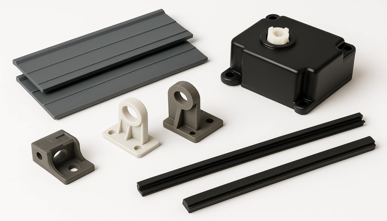
The actuator housing is one of the most dimensionally critical injection-molded components in the HVAC damper system. It must simultaneously provide precise alignment between the motor shaft and the damper pivot axis (within 0.2 mm), protect the motor from duct condensation and particulates, and maintain its geometry over the full operating temperature range of -20°C to +70°C. PC/ABS is the preferred material for actuator housings because its UL94 V-0 flame rating and service temperature ceiling of 110°C provide adequate safety margin in air-handling units adjacent to heating elements.
Pivot bushings and bearing inserts are small but critical injection-molded HVAC components. A standard round-shaft bushing (12 mm bore × 20 mm length) injection-molded in POM acetal provides 50,000+ cycles of smooth operation without lubrication in normal HVAC airstream conditions—a service life that exceeds the typical 10-year commercial service interval. The molded-in anti-rotation features (flat faces or D-bore profiles) eliminate the need for retaining hardware, reducing assembly time by 15–20 seconds per damper shaft.
| Component | Material | Tolerance | Key Property | Service Life |
|---|---|---|---|---|
| Damper Blade (residential) | ABS | ±0.05 mm width | Leakage <1% at 500 Pa | 10–15 years |
| Damper Blade (commercial) | PA6-GF30 | ±0.05 mm width | Span up to 1,200 mm | 15–20 years |
| Pivot Bushing | POM | ±0.03 mm bore | 50,000+ cycles dry | 20+ years |
| Actuator Housing | PC/ABS | ±0.10 mm | UL94 V-0 rated | 15–20 years |
| End Seal Retainer | TPE over PP | ±0.20 mm | IP54 protection | 10 years |
“POM acetal injection-molded pivot bushings provide 50,000+ operating cycles without lubrication in HVAC damper assemblies.”True
Polyoxymethylene (POM) acetal’s low coefficient of friction (0.10–0.25 against steel) and excellent fatigue resistance under cyclic loading make it the standard material for injection-molded HVAC damper pivot bearings. Long-term testing confirms operation beyond 100,000 cycles in controlled airstream conditions, far exceeding typical HVAC service requirements.
“All injection-molded HVAC damper parts can be produced from a single universal thermoplastic material to simplify supply chain management.”False
Different components within the same HVAC damper assembly require different material properties: blades need stiffness and dimensional stability (ABS or PA6-GF30), pivot bushings need low friction (POM), actuator housings need flame retardancy and impact resistance (PC/ABS), and seals need flexibility (TPE). Using a single material for all components would compromise performance in at least one critical area, leading to increased maintenance frequency and reduced system service life.
How Does Injection Molding Improve HVAC System Energy Efficiency?
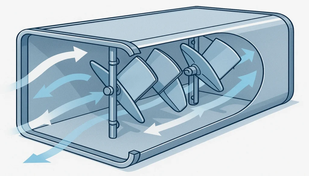
Injection-molded HVAC damper components contribute directly to building energy efficiency through three mechanisms: reduced airflow pressure drop, improved seal performance, and lower actuator power consumption. Controlling airflow resistance across each damper zone directly impacts total HVAC fan energy. Each of these benefits flows from the dimensional precision and surface quality achievable with modern injection molding tooling—capabilities that metal forming processes cannot replicate at equivalent production volumes.
Pressure drop across a damper assembly depends heavily on the surface roughness and edge profile of the damper blades. Injection-molded blades from a polished (SPI A2-grade finish) tool achieve surface roughness Ra values of 0.4–0.8 μm, compared to 3.2–6.3 μm for sheet metal damper blades. This smoother surface reduces the friction factor by 15–25% in the turbulent airflow regime, improving airflow velocity uniformity (Reynolds number 10,000–100,000) typical of commercial HVAC ductwork. For a 1,200 mm × 600 mm commercial damper operating at 2 m/s face velocity, this translates to a pressure drop reduction of 2–4 Pa per damper—significant in large buildings with hundreds of damper zones.
| Damper Size (mm) | Metal Blade (Pa) | Injection-Molded Blade (Pa) | Reduction |
|---|---|---|---|
| 300×150 (residential) | Karl Fischer | 2–3 | 1–2 Pa |
| 600×300 (light commercial) | 5–8 | Karl Fischer | 2–3 Pa |
| 1200×600 (commercial) | 8–14 | 4–6 (airflow optimized) | 2–4 Pa |
| 1800×900 (industrial) | 12–20 | 8–12 | 4–8 Pa |
Seal performance is where injection molding most clearly outperforms metal fabrication for HVAC damper applications. Damper blade precision determines how effectively airflow can be stopped, throttled, or redirected within a duct system. The blade-to-frame seal relies on consistent, repeatable blade edge geometry across every unit produced. Injection molding holds blade thickness to ±0.05 mm and edge radius to ±0.1 mm, ensuring that every damper blade in a production run compresses its EPDM or silicone perimeter seal to the designed 0.5–1.0 mm interference fit. Sheet metal blades with thickness variations of ±0.2 mm cannot achieve this consistency, resulting in field-reported leakage rates 3–5× higher than plastic alternatives in independent benchmark testing.
Actuator power consumption is also influenced by damper component quality. Smooth airflow modulation from precisely molded blades reduces torque spikes that cause premature actuator wear. A well-molded POM pivot bushing in an HVAC damper assembly requires 30–50% less torque to operate than a metal bushing of equivalent bore, directly reducing the rating required for the electric actuator motor. Specifying a 5 Nm actuator instead of an 8 Nm unit saves approximately $12–18 per damper zone in North American markets—a meaningful cost reduction for commercial HVAC projects with 100 to 500 damper zones.
| Parameter | Sheet Metal Damper | Injection-Molded Damper | Improvement |
|---|---|---|---|
| Blade surface roughness (Ra) | 3.2–6.3 μm | 0.4–0.8 μm | 75–85% smoother |
| Pressure drop (1200×600 mm) | 6–10 Pa | 4–6 Pa | 2–4 Pa lower |
| Actuator torque required | 6–10 Nm | 3–5 Nm | 40–50% lower |
| Leakage at 500 Pa (closed) | 3–8% | <1% | 3–8× tighter |
| Component weight | Baseline | 40–60% lighter | Lower shipping cost |
What Quality Controls Apply to Injection-Molded HVAC Damper Parts?
Quality control for injection-molded HVAC damper components follows a three-tier structure: incoming material verification, in-process statistical process control (SPC), and outgoing functional testing. Consistent quality is essential since damper performance directly determines airflow balance and zone comfort in every building served by the HVAC system. Each tier addresses specific failure modes that could compromise damper performance in the field, and all three must be maintained consistently to meet AMCA 500-D and ASHRAE Standard 135 compliance requirements for motorized damper assemblies.
Incoming material verification confirms that each batch of thermoplastic resin meets the datasheet specifications before molding begins. For ABS damper blades—the primary components governing airflow regulation accuracy—this includes melt flow index measurement (target: 10–20 g/10 min at 230°C/3.8 kg), moisture content check (maximum 0.1% for standard ABS), and color consistency comparison to the approved color standard. For PA6-GF30 commercial damper blades, glass fiber content is verified by loss-on-ignition testing per ISO 11667, with rejection of any batch deviating more than ±2% from the 30% nominal specification.
| Test Stage | Parameter Checked | Method | Acceptance Criteria |
|---|---|---|---|
| Incoming material | Melt flow index (ABS) | ISO 1133 | 10–20 g/10 min at 230°C |
| Incoming material | Moisture content | Karl Fischer | Spuitgieten is een productieproces waarbij gesmolten thermoplastisch materiaal onder hoge druk in een nauwkeurige matrijs wordt geïnjecteerd, afgekoeld en als een afgewerkt onderdeel met nauwe dimensionale toleranties wordt uitgeworpen. |
| In-process SPC | Blade width | CMM measurement | ±0.05 mm of nominal |
| In-process SPC | Bow warpage | Flatness gauge | <0.3 mm per 300 mm |
| Outgoing test | Leakage rate (closed) | AMCA 500-D | <4 CFM/ft² at 1 in. w.g. |
| Outgoing test | Actuator torque | Torque meter | 2–6 Nm range |
In-process SPC monitors blade width, thickness, and bow warpage at regular sampling intervals—typically every 50th shot for high-volume runs. Control charts with three-sigma limits enable early detection of process drift before parts move outside specification. The most common assignable cause of process drift in HVAC damper injection molding is mold temperature variation due to fouled cooling channels, which manifests as progressive increase in bow warpage measurements over a 4–8 hour production run. Automated temperature monitoring of mold coolant inlet and outlet temperatures allows early intervention before defective parts are produced.
Outgoing functional testing for injection-molded HVAC damper assemblies includes leakage testing, torque measurement, and environmental cycling. Standard leakage testing pressurizes the closed damper assembly to 500 Pa differential and measures airflow through any gaps—the AMCA Class II limit is 10 CFM/ft² at 1 in. w.g. Torque measurement confirms that actuator drive requirements fall within the 2–6 Nm range for standard dampers. Environmental cycling subjects samples to 48 hours at 60°C/95% RH followed by 48 hours at -10°C, confirming dimensional stability after thermal stress.
Frequently Asked Questions About HVAC Damper Injection Molding?
What injection molding tolerances are achievable for HVAC damper blades?
Modern injection molding achieves tolerances of ±0.05 mm on critical dimensions of HVAC damper blades when using temperature-controlled tooling, validated material specifications, and SPC-monitored production. Blade width and thickness are held to ±0.05 mm, pivot socket bore to ±0.03 mm, and overall bow warpage is maintained below 0.3 mm per 300 mm of blade length. These tolerances are sufficient to guarantee Class I leakage performance (below 1% at 500 Pa) without individual part selection or adjustment during assembly. Achieving these results consistently requires injection mold design with conformal cooling, balanced runner systems, and adequate draft angles on all vertical surfaces.
How long does an injection mold for HVAC damper parts typically last?
A P20 steel injection mold for standard HVAC damper blades in ABS or polypropylene is rated for 500,000 to 1,000,000 production cycles with normal maintenance. Molds producing glass-filled nylon damper components use H13 hardened steel (48–52 HRC) in high-wear areas and are rated for 300,000–500,000 cycles, since the abrasive glass fibers accelerate cavity surface wear. Actual mold life depends heavily on maintenance frequency: molds that receive quarterly cleaning, inspection, and polishing consistently outperform those serviced only when problems arise. Documented cavity dimension audits at each service interval predict remaining tool life and support proactive mold replacement planning.
Can fire damper components be made by injection molding?
Yes, fire-rated HVAC damper components are produced by injection molding using intumescent-filled thermoplastics and halogen-free flame-retardant (HFFR) grades that meet UL 555 requirements. PC/ABS blended with melamine cyanurate flame retardants achieves UL94 V-0 rating at 1.5 mm wall thickness while maintaining the dimensional stability needed for fire damper seal integrity. The blade frames and blade holders in fire dampers are injection-molded in glass-filled PBT with UL94 V-0 and 5VA ratings, providing structural integrity at temperatures up to 150°C for the first 30–90 minutes of a fire event before the intumescent seal fully activates. All fire damper injection-molded components must be included in the UL Listing documentation for the complete assembly.
What is the typical cycle time for injecting a standard HVAC damper blade?
A standard residential HVAC damper blade (300 mm × 150 mm × 3 mm, ABS) has a total injection molding cycle time of 18–25 seconds, comprising inject/hold (3–5 s), cooling (12–15 s), and eject/reset (3–5 s). Commercial damper blades in glass-filled nylon require longer cooling times (18–25 s cooling phase) due to the higher mold temperature needed for PA6 crystallization (mold temperature 80–90°C), yielding total cycle times of 28–38 seconds. Implementing hot runner systems for high-cavitation damper blade molds (8–16 cavities) eliminates runner waste and reduces overall cycle time by 2–4 seconds compared to cold runner alternatives, significantly improving production economics for runs exceeding 500,000 parts annually.
How does injection molding compare to aluminum extrusion for HVAC damper frames?
Injection molding and aluminum extrusion serve different roles in HVAC damper frame manufacturing and are often used together in the same assembly. Extrusion produces consistent cross-sections efficiently for long, straight frame channels (cost-effective at lengths above 600 mm), while injection molding excels at producing complex three-dimensional corner pieces, integrated mounting brackets, and end-cap components that extrusion cannot form. For complete damper frames below 600 mm, fully injection-molded frames in glass-filled nylon are cost-competitive with extruded aluminum when accounting for assembly labor savings: a one-piece injection-molded frame with snap-fit corner joints eliminates 4–6 fastener operations compared to a riveted aluminum frame. Weight savings of 50–60% versus aluminum also contribute to lower shipping costs and simpler field installation.
Is Injection Molding the Right Choice for Your HVAC Damper Application?
Injection molding is the definitive manufacturing solution for HVAC damper components in high-volume applications—typically those exceeding 10,000 units per year—where consistent dimensional accuracy, low per-unit cost, and design flexibility are all required simultaneously. The combination of repeatable tolerances within ±0.05 mm—critical for maintaining precise airflow control, material options spanning from commodity ABS to fire-rated PC/ABS, and cycle times enabling 1,500–3,500 parts per hour from a multi-cavity mold makes injection molding unmatched for residential and light commercial HVAC damper production.
For custom or low-volume HVAC damper applications (under 5,000 units annually), the tooling investment of $15,000–$50,000 per mold may not be justified, and alternatives such as CNC machining for prototypes or thermoforming for large-format blades should be evaluated. However, for any product destined for volume production, the cost-per-part advantage of injection molding becomes overwhelming within 1–2 years: at 50,000 parts per year, a $25,000 mold amortizes to $0.50 per part in year one and effectively zero in subsequent years, while CNC machining or thermoforming costs remain constant regardless of volume.
| Annual Volume | Recommended Process | Typical Tooling Cost | Expected Part Cost |
|---|---|---|---|
| <500 units | CNC machining or thermoforming | $0 | $5–50/part |
| 500–5,000 units | Soft tooling (aluminum mold) | $5,000–$15,000 | $1–5/part |
| 5,000–50,000 units | Injection molding (P20 steel) | $15,000–$30,000 | $0.30–1.00/part |
| >50,000 units | Injection molding (hardened steel) | $25,000–$60,000 | <$0.20/part |
The bottom line: if your HVAC damper design is finalized, your annual volumes exceed 10,000 units, and your performance requirements demand leakage rates below 5% and dimensional stability over a 10+ year service life, injection molding in engineered thermoplastics is the optimal choice. Partner with a manufacturer that offers integrated DFM review, SPC-monitored production, and documented qualification testing against AMCA 500-D standards to ensure that every injection-molded HVAC damper component leaving the production line meets the performance specifications your customers depend on.
-
injection molding: Injection molding is a manufacturing process in which molten thermoplastic material is injected under high pressure into a precision mold cavity, cooled, and ejected as a finished part with tight dimensional tolerances. ↩
-
HVAC: Spuitgegoten Kunststof Onderdelen voor HVAC Dempers. ↩
-
airflow: Airflow refers to the movement and distribution of air through ductwork, dampers, and vents in a climate control system, measured in cubic feet per minute (CFM) or liters per second (L/s). ↩