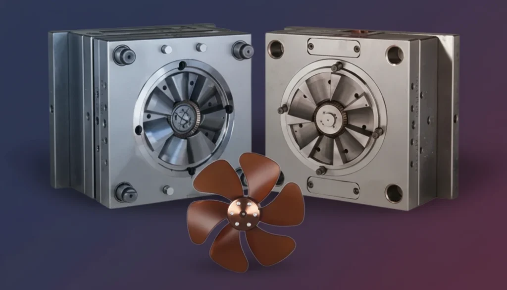
– Precision in plastic fan blade manufacturing directly correlates to aerodynamic efficiency and noise reduction in HVAC systems.
– Mold flow analysis is critical for predicting fiber orientation and warpage, ensuring the final airfoil geometry matches design intent.
– High-performance polymers like Glass-Fiber Reinforced Polypropylene (PP-GF) offer the best balance of weight, stiffness, and cost.
– Gate location and cooling channel design significantly impact the dynamic balance and structural integrity of injection molded fans.
What Defines High-Efficiency Plastic Fan Blade Manufacturing?
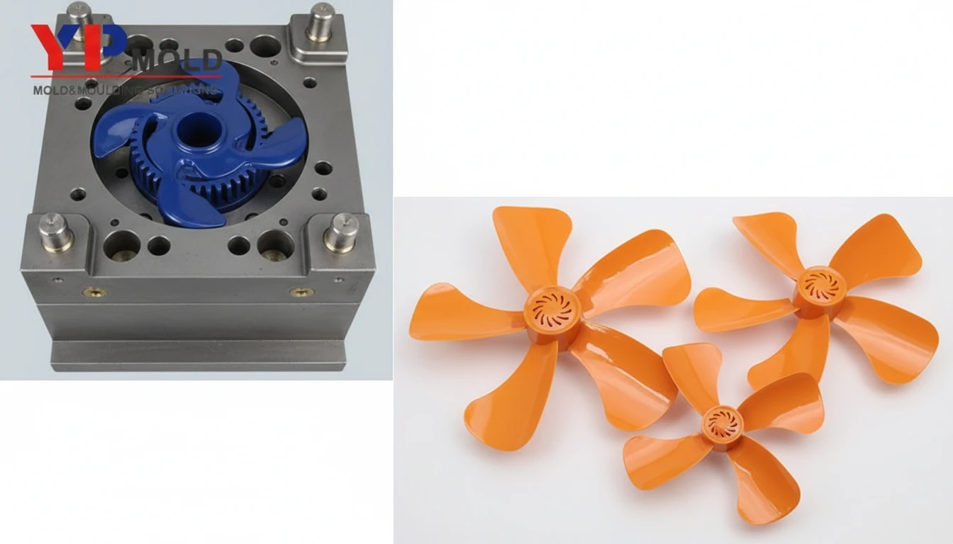
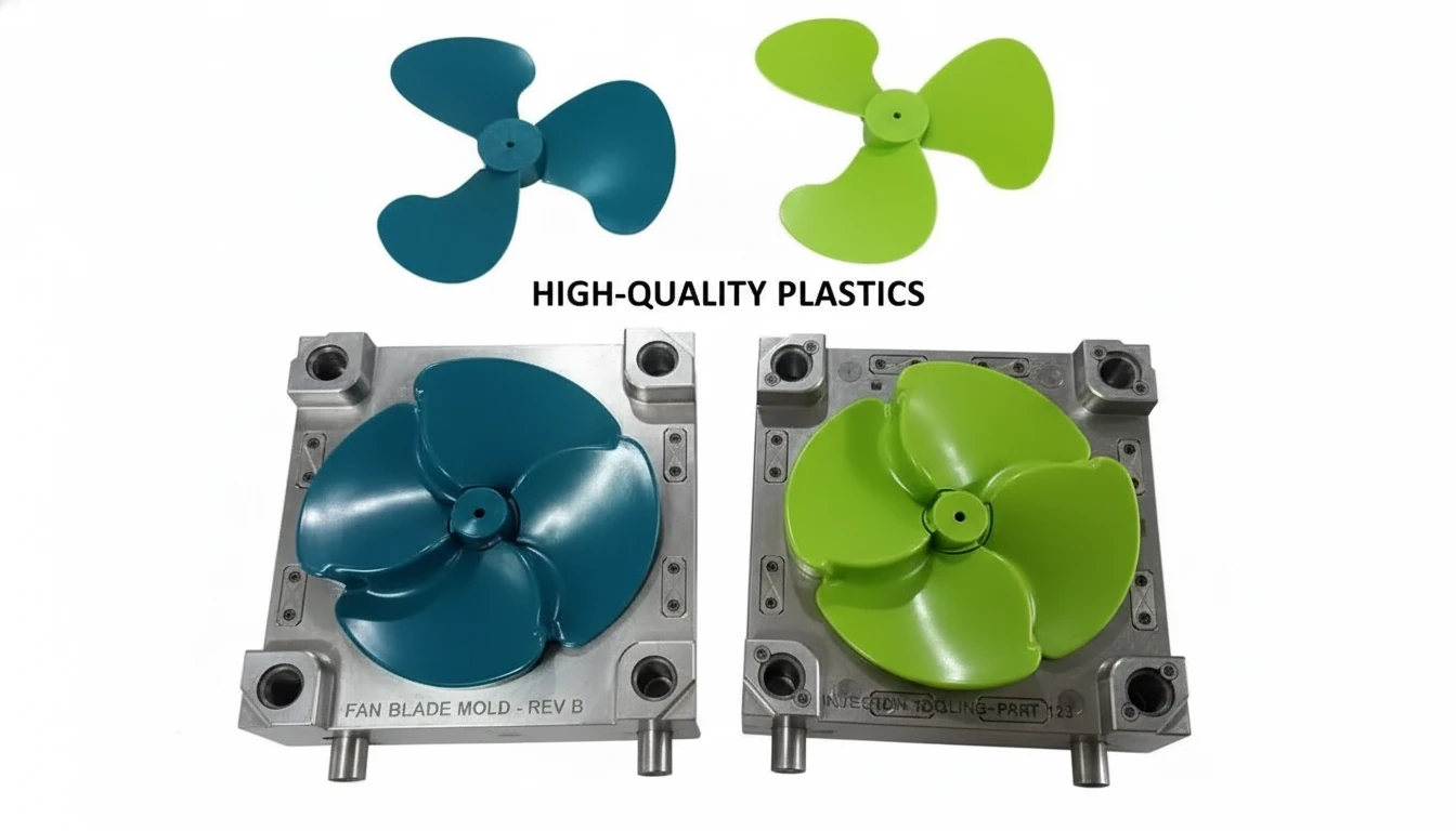
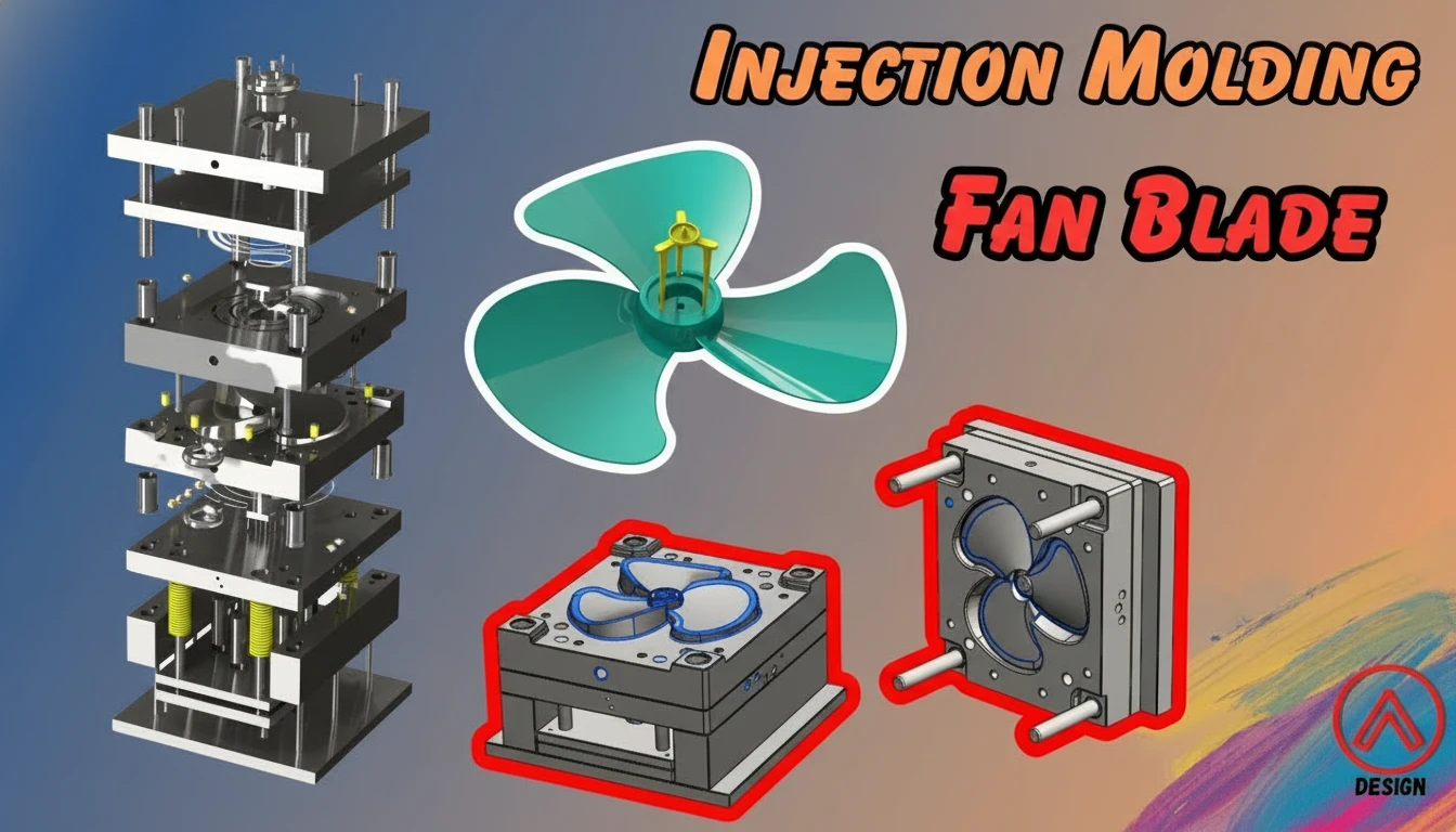
Plastic fan blade manufacturing for Heating, Ventilation, and Air Conditioning (HVAC) is the process of creating complex, airfoil-shaped impellers using injection molding technologies. Unlike metal stamping or casting, injection molding allows for variable wall thicknesses, integrated hubs, and complex aerodynamic curves (twist and camber) that maximize air movement while minimizing energy input.
Mold Flow Analysis (MFA) is the computer-aided engineering (CAE) simulation of the injection molding process. In the context of fan blades, MFA is utilized to predict how molten polymer fills the mold cavity, how fibers align (anisotropy), and crucially, how the part deforms (warps) during cooling. This ensures the physical part retains the intended aerodynamic design.
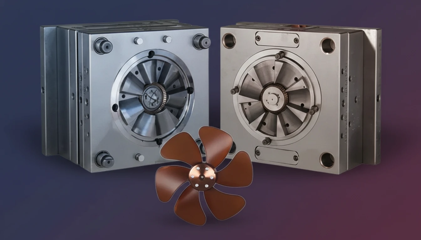
What Are the Critical Parameters for Injection Molded HVAC Fans?
To achieve HVAC airflow optimization1, the manufacturing process must adhere to strict parameters. Deviations in these values lead to turbulence, noise, and reduced static pressure.
| Parameter | Typical Value / Range | Unit | Critical Note |
|---|---|---|---|
| Blade Wall Thickness | 2.5 – 5.0 | mm | Must taper from root to tip for stress distribution; abrupt changes cause sink marks. |
| Thickness Tolerance | ±0.05 | mm | Variations cause dynamic imbalance and vibration. |
| Material Shrinkage | 0.4 – 1.5 | % | Depends on fiber content; anisotropic shrinkage must be compensated in mold design. |
| Glass Fiber Content | 15 – 40 | % | Higher content increases stiffness (modulus) but increases warpage risk. |
| Ejection Temperature | 80 – 110 | °C | Ejecting too hot causes distortion; too cold increases cycle time. |
| Surface Finish (SPI) | A2 or B1 | – | Smoother finishes reduce drag on the blade surface. |
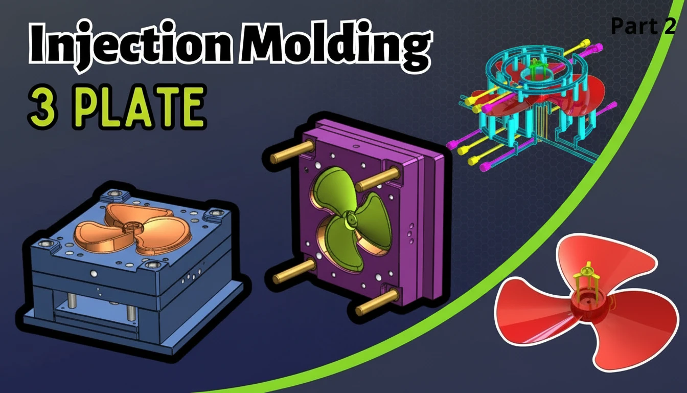
How Does Mold Flow Analysis Impact Aerodynamic Design?
The intersection of mold flow analysis and aerodynamics is where efficiency is won or lost. An aerodynamicist designs a blade for optimal lift-to-drag ratio. However, the injection molding process introduces residual stresses2 that can twist the blade away from this ideal shape.
Step-by-Step Simulation Workflow:
- Gate Location Optimization:
- Métrologie en ligne : Ensure uniform filling to minimize imbalance.
- Action: Place gates (usually diaphragm or pin gates) at the fan hub.
- Result: Radial flow creates concentric fiber alignment, improving hoop strength.
- Fiber Orientation Prediction:
- Métrologie en ligne : Predict strength and shrinkage direction.
- Action: MFA software calculates how glass fibers align with flow.
- Insight: Fibers aligned along the blade length increase bending stiffness; random orientation creates weak spots.
- Warpage Compensation (Windage):
- Métrologie en ligne : Counteract deformation.
- Action: The mold cavity is cut slightly "wrong" (biased inverse to the predicted warp) so the part cools into the "right" shape.
- Result: The final injection molded fan maintains the precise angle of attack required for efficiency.
Glass fibers align with flow, causing the material to shrink differently across the length and width (anisotropy), which is the primary driver of warpage in reinforced blades.
While clips correct minor imbalances, precise mold flow control and cavity balancing can produce 'mold-balanced' fans that require zero or minimal post-process correction.
Which Materials Enable Optimal HVAC Airflow Optimization?
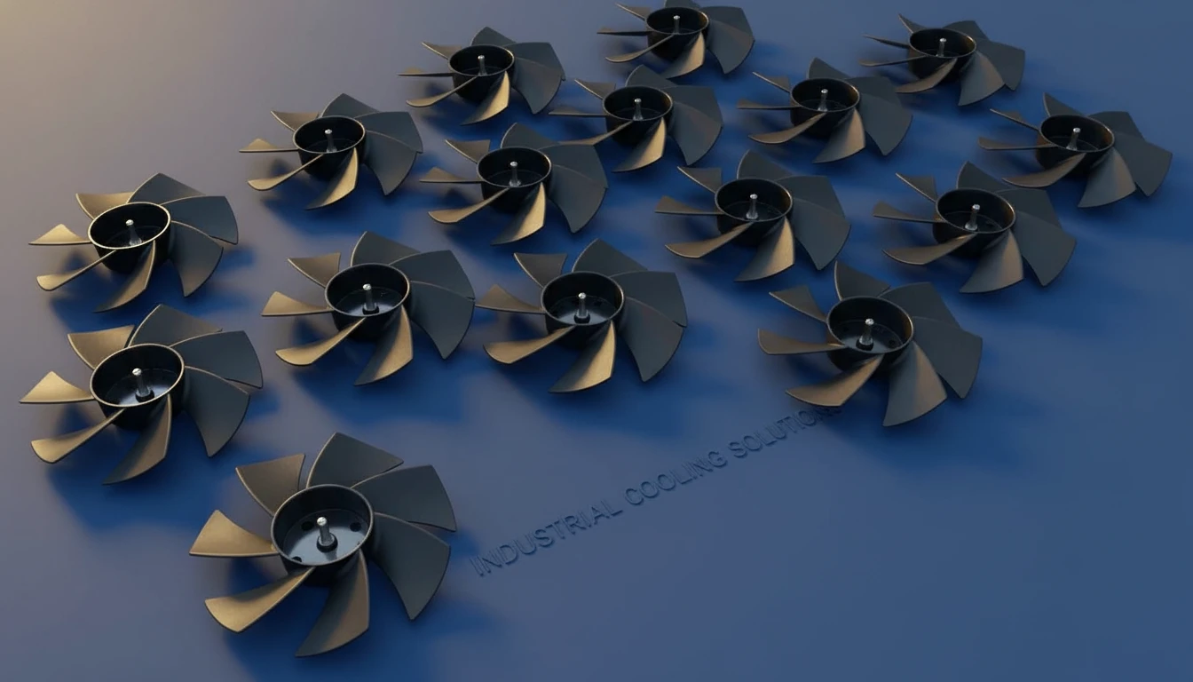
Selecting the right material is a trade-off between structural rigidity, weight, and fatigue resistance.
- Polypropylene (PP) + Glass Fiber (GF): The industry standard for residential and light commercial units. It offers low density (lightweight), chemical resistance, and cost-effectiveness.
- Polyamide 6 or 66 (PA6/PA66) + Glass Fiber: Used for high-speed, high-temperature industrial fans. PA absorbs moisture, which can affect dimensional stability, so it requires conditioning.
- Polybutylene Terephthalate (PBT) + GF: Excellent dimensional stability and low moisture absorption. Used where precise tolerances are non-negotiable.
What Are the Advantages and Disadvantages of Injection Molded Fans?
| Feature | Advantages | Polycarbonate (PC) |
|---|---|---|
| Aerodynamics | Allows for complex 3D geometries (twisted airfoils) that metal cannot easily achieve, boosting efficiency. | Large diameter fans (>1 meter) may suffer from deflection under high loads compared to metal. |
| Weight | Significantly lighter than metal, reducing motor load and starting torque requirements (energy saving). | Lower ultimate tensile strength compared to steel or aluminum. |
| Noise | Polymer naturally dampens vibration, resulting in quieter operation (lower dB). | Can suffer from creep (deformation over time) under constant high heat/load. |
| Production | High volume scalability with low unit cost after tooling amortization. | High initial tooling cost for complex molds with conformal cooling3. |
How to Implement a Process for Aerodynamic Consistency?
To manufacture injection molded fans that consistently meet airflow targets, follow this step-by-step recommendation:
- Design for Manufacturing (DFM) Review:
- Ensure the hub-to-blade transition has sufficient radii to prevent stress concentrators.
- Verify draft angles do not compromise the active surface area of the blade.
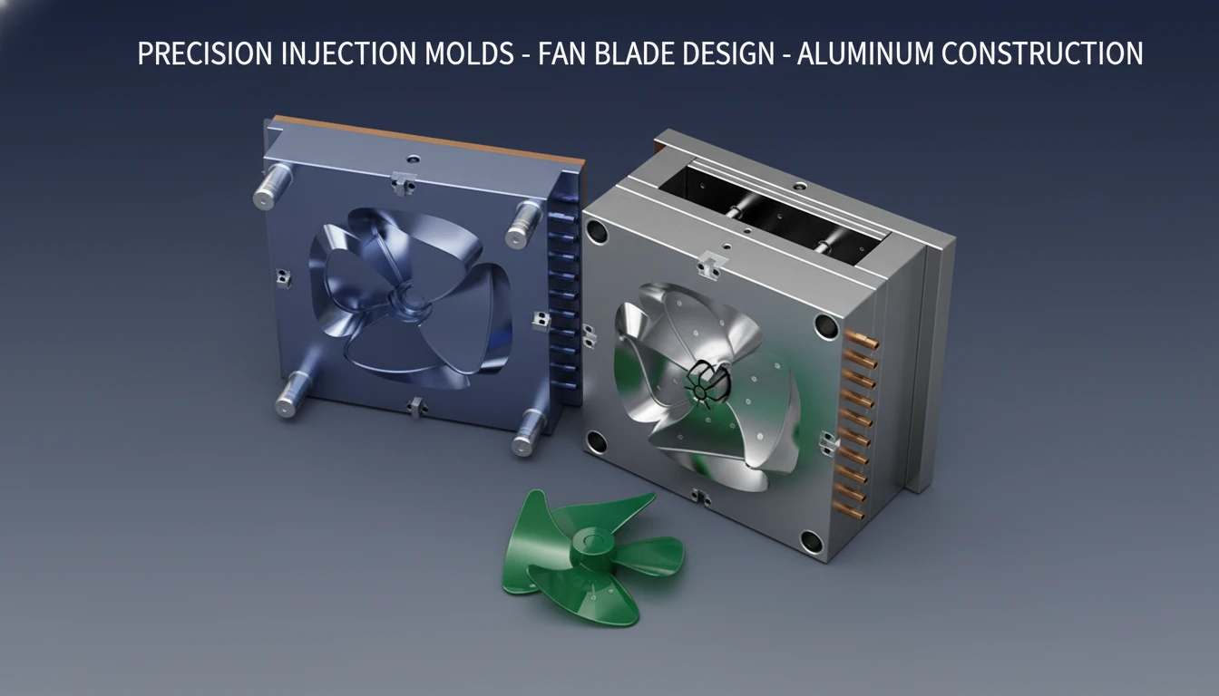
- Conformal Cooling Implementation:
- Use 3D-printed metal mold inserts to run cooling channels inside the curved blade core.
- Benefit: Reduces cooling time and ensures uniform heat removal, minimizing residual stress warpage.
- Scientific Molding Setup:
- Establish a "Decoupled Molding" process. Separate the filling phase from the packing phase.
- Use cavity pressure sensors to detect viscosity changes and switch over consistently.
- In-Line Metrology:
- Optimiser l'efficacité des ventilateurs CVC moulés par injection.
- Check for "gate vestige" height—if the gate remnant protrudes, it creates turbulence at the hub.
This technology ensures uniform cooling across curved surfaces, significantly reducing cycle time and warpage compared to straight-line cooling.
Excessive pressure creates high internal residual stress, which can lead to stress cracking and warping over time, compromising the fan's lifespan.
Where Are These Optimized Fan Blades Applied?
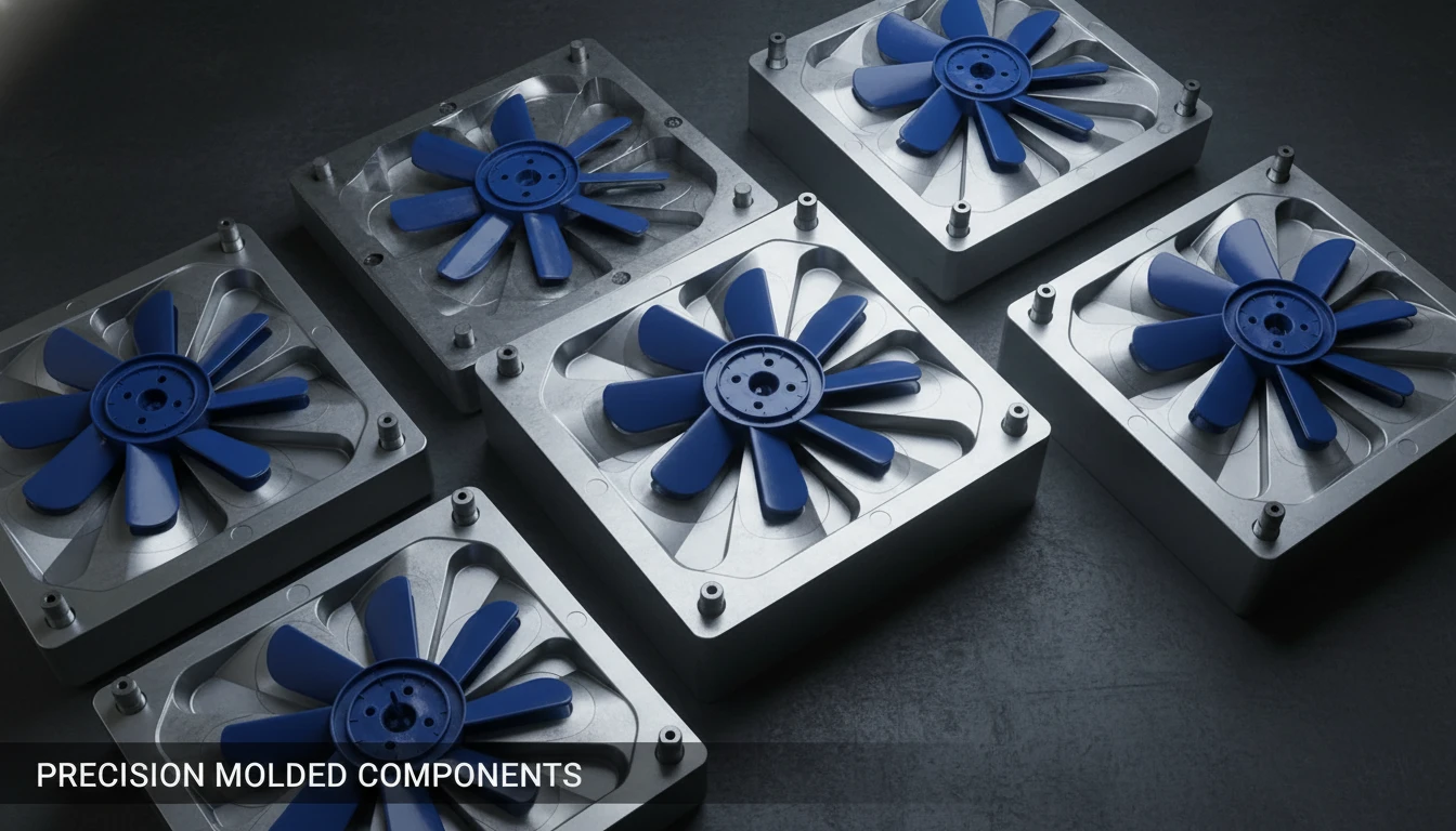
- Residential Air Conditioning Units: Outdoor condenser fans requiring low noise and weather resistance.
- Automotive Cooling Systems: Radiator fans where space is tight and high-temp resistance (PA66-GF) is needed.
- Data Center Cooling: High-static pressure fans designed to push air through dense server racks.
- Industrial Air Handlers: Large diameter impellers focusing on maximizing CFM (Cubic Feet per Minute) per watt.
Frequently Asked Questions (FAQ)
Q1: How does gate location affecting fan balancing?
A: If the gate is not perfectly centered or if multiple gates do not fill evenly, the material density distribution will be uneven. This creates a heavy spot on the fan, causing wobble and vibration at high speeds (RPM).
Q2: Why is glass fiber orientation important in fan blades?
A: Glass fibers provide strength. In plastic fan blade manufacturing4, we want fibers aligned radially (from hub to tip) to resist centrifugal force. If fibers are perpendicular to the load, the blade may snap under high RPM.
Q3: Can 3D printing replace injection molding for HVAC fans?
A: For prototyping, yes. For mass production, no. Injection molding is faster, cheaper, and produces stronger parts with better surface finishes (essential for aerodynamics) than current additive manufacturing methods.
Q4: What causes "weld lines" on a fan blade and why are they bad?
A: Weld lines occur where two flow fronts meet. On a fan blade, a weld line is a structural weak point. If located near the blade root (high stress area), it can lead to catastrophic failure. Mold flow analysis5 helps position these in low-stress areas.
Q5: How does surface texture affect airflow?
A: generally, a polished surface (SPI A2) is preferred to minimize friction drag. However, some advanced designs use specific micro-textures (like shark skin or dimples) to delay flow separation and reduce noise, though this is difficult to mold consistentl.
Summary
Optimizing HVAC airflow begins long before the fan is installed; it starts in the mold design phase. By leveraging mold flow analysis to predict fiber orientation and warpage, manufacturers can produce injection molded fans6 that retain their complex aerodynamic design. Utilizing reinforced materials like PP-GF or PA-GF, combined with precision cooling strategies, allows for the creation of blades that are lighter, quieter, and more energy-efficient than traditional metal counterparts. The key to success lies in controlling the variable shrinkage of plastics to ensure the physical part matches the theoretical airfoil.
-
Discover effective methods for optimizing airflow in HVAC systems for better performance. ↩
-
Discover the impact of residual stresses on the performance and longevity of fan blades. ↩
-
Discover how conformal cooling enhances the injection molding process for fan blades. ↩
-
Explore how plastic fan blade manufacturing enhances efficiency and reduces noise in HVAC systems. ↩
-
Learn about the critical role of mold flow analysis in ensuring optimal fan blade design and performance. ↩
-
Find out how injection molded fans can enhance performance and efficiency in HVAC applications. ↩