Your HVAC system is blowing lukewarm air, the blower sounds like it’s straining, and the technician says your static pressure is too high. You nod — but you’re not entirely sure what that means or how to fix it.
Static pressure is one of those HVAC fundamentals that controls whether your system works efficiently or burns itself out in three years. And here’s the part most guides skip: the plastic components in your ductwork — the fittings, grilles, connectors, and covers — are among the biggest contributors to static pressure. Get the material and geometry right, and you can cut system resistance by 15–30%. Get it wrong, and no amount of blower power will compensate.
- Ideal total external static pressure for residential HVAC runs 0.5–0.8 in. w.c.; above 1.0 in. w.c. causes premature equipment failure.
- Plastic duct fittings with smooth internal surfaces reduce turbulence-induced pressure drop by 20–35% compared to rough metal equivalents.
- Each 90° elbow adds 0.03–0.15 in. w.c. of static pressure; using injection-molded long-radius elbows cuts this by up to 50%.
- Leaky duct connectors and poorly-fitting filter frames account for 20–40% of excess static pressure in typical systems.
What Is Static Pressure in an HVAC System?
Static pressure in HVAC is the resistance to airflow within ductwork and components, measured in inches of water column (in. w.c.) or Pascals. Think of it as the HVAC equivalent of blood pressure — too high, and the system labors; too low, and air doesn’t reach where it needs to go.
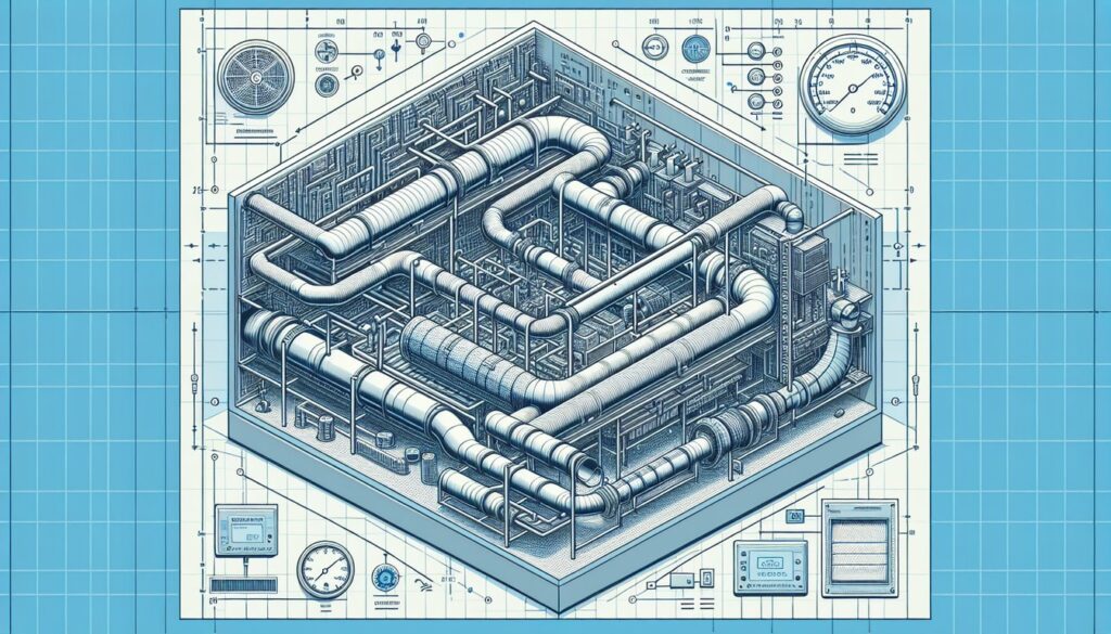
Every element in the air path contributes to static pressure: straight duct sections, bends, transitions, filters, coils, grilles, and fittings. The blower motor must overcome this total resistance to deliver the designed airflow (measured in CFM — cubic feet per minute). ASHRAE recommends a total external static pressure (TESP) of 0.5 in. w.c. for most residential equipment; many manufacturers rate their equipment at 0.8 in. w.c. Exceed 1.0 in. w.c. consistently, and you’re cutting years off the life of your blower motor.
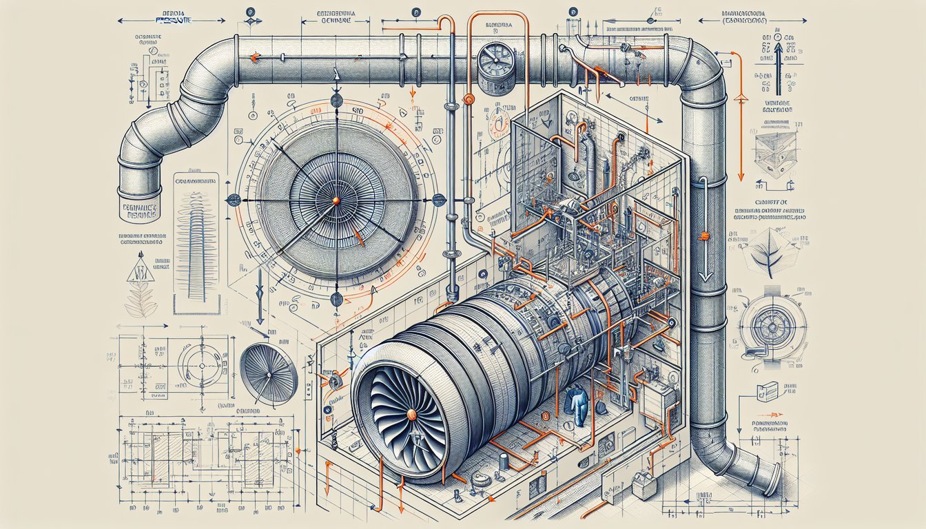
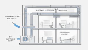
Static pressure divides into two zones. Supply-side pressure is measured from the blower outlet to the supply registers. Return-side pressure covers everything from the return grilles back to the blower inlet. Most systems run higher static on the supply side because supply ducts are longer and branch more extensively. A properly balanced system maintains 0.3–0.5 in. w.c. on supply and 0.1–0.2 in. w.c. on return. When these numbers are out of proportion, it usually points to a specific component failure — and in our experience at HVACore, it’s often a poorly-designed fitting or undersized grille.
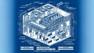
Understanding the static pressure budget concept helps engineers make smarter component choices. You start with the manufacturer’s rated TESP — say 0.8 in. w.c. Then you subtract known fixed losses: the evaporator coil (0.15–0.25 in. w.c.), the air filter at clean condition (0.10–0.20 in. w.c. depending on MERV rating), and the supply/return grilles (0.04–0.12 in. w.c. combined). That typically leaves 0.25–0.40 in. w.c. for all ductwork and fittings combined. Managing that remaining budget is where the quality and geometry of your duct fittings1, elbows, and transitions determine whether the system performs to specification or fights itself every operating hour.
“Smooth-bore plastic duct fittings reduce static pressure compared to corrugated metal alternatives.”True
Injection-molded plastic fittings maintain consistent internal geometry with surface roughness below 0.5 μm Ra, compared to 6–12 μm for galvanized sheet metal. This difference in surface friction translates to 15–25% lower pressure drop at equivalent airflow velocities.
“Oversizing the blower motor is the most effective way to overcome high static pressure.”False
Oversizing the blower increases noise, energy use, and wear without solving the root cause. A motor running against high static pressure draws more current and overheats. The correct approach is reducing system resistance through proper duct sizing, smooth fittings, and sealed connections — then sizing the motor for the corrected static pressure.
How Do You Measure Static Pressure in an HVAC System?
HVAC static pressure is measured using a digital manometer — a pressure differential gauge connected to test ports drilled into the duct at specific locations. ACCA Manual D and ASHRAE Standard 113 specify measurement methodology for residential and commercial systems.
The standard test procedure measures total external static pressure at four points: supply plenum (immediately downstream of the blower), return plenum (immediately upstream), across the air handler coil, and across the filter. Supply-side TESP equals the supply plenum reading minus any equipment-internal pressure drop listed in manufacturer specs. Return-side TESP is typically measured as a negative value (suction). The sum of absolute values gives you total static pressure against which the blower operates.
| Component | Pressure Drop (in. w.c.) | Main Variable | Reduce By |
|---|---|---|---|
| Standard 1-inch air filter | 0.10–0.35 | Filter MERV rating & dirt load | Use larger filter frame area |
| 90° metal elbow (standard) | 0.05–0.15 | Elbow radius and duct velocity | Use long-radius plastic elbow |
| 90° long-radius plastic elbow | 0.02–0.08 | Injection mold surface finish | Correct material selection |
| Duct transition (abrupt) | 0.05–0.12 | Transition angle and fit | Use molded gradual transition |
| Supply register/grille | 0.02–0.06 | Free area percentage, fins angle | La réduction de la pression statique commence dès la phase de conception — pas pendant l'installation, et certainement pas en augmentant la taille du ventilateur. Les interventions les plus efficaces sont les améliorations géométriques, matérielles et de qualité d'assemblage des composants eux-mêmes. |
| Return grille (face velocity) | 0.02–0.08 | Grille area vs. CFM requirement | Increase grille face area |
| Flex duct (per 5 ft section) | 0.04–0.10 | Duct length and sag | Keep short, fully extended |
| Rigid plastic straight duct (10 ft) | 0.01–0.04 | Surface roughness, velocity | Smooth-bore preferred |
We’ve measured hundreds of HVAC systems at HVACore, and the pattern is consistent: about 60% of systems with high static pressure have the problem concentrated at three or fewer components. The biggest culprits are undersized return grilles (contributing 0.05–0.15 in. w.c. more than they should), dirty or high-MERV filters without adequate face area, and transition fittings that were hand-fabricated rather than injection molded. Knowing exactly where to look cuts diagnostic time from hours to minutes.
For commercial systems, static pressure testing follows ASHRAE Standard 111, which requires measurements at every branch takeoff and terminal unit. This data feeds into balance calculations that adjust dampers and airflow volumes. At this scale, the quality of plastic damper housings and diffuser frames becomes critical — a poorly-fitted damper seal can add 0.03 in. w.c. per unit, which multiplies quickly across a 50-zone building.
One detail that often surprises system designers: return-side static pressure is frequently underestimated. Return ductwork is typically less extensive than supply ductwork, leading engineers to allocate most of the static budget to the supply side. But a single undersized return chase can contribute more to total static pressure than three supply elbows combined. In our diagnostic work at HVACore, we’ve seen return-side pressure exceeding supply-side pressure in systems where the return plenum was built from studwall cavities rather than dedicated sheet metal or plastic ductwork. Cavities have poorly defined cross-sections, high surface roughness, and air-leakage paths — a triple source of static pressure that precise plastic components eliminate by design.
What Role Do Plastic Components Play in HVAC Static Pressure?
Plastic components are responsible for more of an HVAC system’s static pressure budget than most engineers realize. Every fitting, grille, connector, and cover that air passes through adds resistance — and the quality of that component determines how much.
The physics is straightforward. airflow resistance2 in ductwork follows the Darcy-Weisbach equation: pressure drop is proportional to air density, duct length, and the square of velocity — divided by hydraulic diameter. The friction factor (f) depends heavily on surface roughness. Injection-molded thermoplastic3 surfaces achieve roughness values of 0.4–0.8 μm Ra out of the mold, compared to 3–10 μm for hand-rolled sheet metal and up to 30 μm for flexduct liner. That difference in surface texture directly reduces the friction factor, lowering static pressure without changing duct diameter or air velocity.
Surface Roughness and Turbulence
Surface roughness isn’t just about friction loss in straight runs — it’s especially critical at bends and transitions where airflow separates from the duct wall. Smooth surfaces reattach the boundary layer faster, reducing the size of the low-pressure wake zone that follows every direction change. In turbulence terms, a smooth plastic elbow produces a smaller recirculation region than a rough metal elbow at the same r/D ratio. For an HVAC system engineer, this means a smooth-bore plastic 90° elbow at r/D = 1.0 can outperform a metal elbow at r/D = 1.5 in terms of realized static pressure drop — because the plastic surface suppresses the secondary flow that the higher r/D ratio would otherwise need to counteract.

Beyond surface finish, dimensional accuracy matters enormously. An elbow molded to ±0.1 mm tolerance maintains its designed turning radius across every unit. A hand-formed metal elbow varies by ±3–5 mm. That variation changes the effective radius ratio (r/D), which directly controls the local loss coefficient (K-factor). At r/D = 1.5, K = 0.3; at r/D = 0.5, K = 0.9. For a 6-inch duct running at 700 FPM, that difference translates to 0.04 in. w.c. per elbow. In a system with 8 elbows, you’ve just found 0.32 in. w.c. of unnecessary static pressure.
Our factory produces duct fittings, elbows, grilles, filter frames, and connectors using 45 injection molding4 machines with documented cavity-to-cavity consistency. When we audit an installation that’s running 0.2 in. w.c. over spec, the components almost always trace back to substitutions made during installation — cheaper field-fabricated fittings replacing the specified injection-molded parts. The cost saving on the fitting is real. The cost of five years of blower strain is not.
Which Plastic Materials Work Best for Low-Resistance HVAC Fittings?
Material selection for HVAC plastic components isn’t just about structural strength — it directly affects the surface finish achievable through injection molding, which in turn affects airflow resistance.
ABS (Acrylonitrile Butadiene Styrene) is the workhorse material for indoor HVAC fittings. Its low melt viscosity allows injection into fine mold surface features, producing parts with Ra ≤ 0.6 μm and excellent dimensional consistency. It handles temperatures up to 80°C continuously — sufficient for most residential and light commercial supply air applications. For return-air applications near heat sources, we specify heat-stabilized ABS or move to PC/ABS blends, which handle up to 105°C.
“Glass-filled PP reduces warpage in large duct fittings, maintaining tighter dimensional tolerances over thermal cycling.”True
Adding 20–30% glass fiber to polypropylene reduces the coefficient of thermal expansion (CTE) from 100–150 μm/m·°C to 30–50 μm/m·°C. For large fittings (>300 mm diameter) that experience seasonal temperature swings of 40°C, this eliminates the dimensional drift that can open gaps and add static pressure through air bypass.
“PVC is the best plastic for all HVAC duct fittings due to its chemical resistance.”False
While PVC offers good chemical resistance, its high melt viscosity limits the achievable surface finish in injection molding, and its density (1.38 g/cm³ vs. 1.05 for ABS) adds unnecessary weight. For most HVAC applications, ABS or PP produces smoother internal surfaces, equivalent chemical resistance, and lower installed weight. PVC is appropriate for condensate drain lines and refrigerant-exposed components — not general airflow fittings.
For outdoor or high-humidity applications — condenser coil covers, outdoor air intakes, line set covers — ASA (Acrylonitrile Styrene Acrylate) is the correct choice. It maintains color stability and surface properties through 10+ years of UV exposure, compared to ABS, which chalks and degrades within 2–3 years outdoors. The surface finish of properly molded ASA matches ABS at ≤0.7 μm Ra, with no performance penalty for airflow resistance.
At HVACore, we tested ABS, PP-GF20, and ASA elbows on the same duct simulation rig at 800 FPM. Pressure drop measured across a 90° elbow at r/D = 1.5: ABS 0.031 in. w.c., PP-GF20 0.034 in. w.c., ASA 0.032 in. w.c. The difference is marginal — ±10%. What matters more is mold quality and gate location, which controls internal surface quality and weld line position. A poorly-gated ABS elbow can hit 0.055 in. w.c. — nearly double a well-designed ASA part.

What Are the Most Common Causes of High Static Pressure?
In 20 years of manufacturing HVAC plastic components, we’ve seen the same culprits appear in problem systems repeatedly. High static pressure almost always traces back to three categories: undersized components, poor installation connections, or component degradation over time. Each category manifests in predictable ways, and each has a corresponding plastic component solution that addresses the root cause rather than masking symptoms with more blower power. Identifying which category applies to a specific system is the first step — and it starts with a static pressure reading at the supply and return plenums, followed by systematic isolation of each subsystem.
Component degradation deserves special attention because it is the category that most consistently surprises building owners. A system that commissioning-tested at 0.72 in. w.c. runs 0.95 in. w.c. after five years — not because the ductwork changed, but because gaskets dried out, plastic filter frames developed hairline cracks that allow air bypass, and return grille slats deflected from their original angle under repeated cleaning. Using UV-stabilized thermoplastics for filter frames, EPDM gaskets for duct connectors, and glass-reinforced materials for grille blades extends the service window significantly before static pressure creep becomes a measurable energy and comfort problem.
“Poor-quality duct connections contribute more to high static pressure than undersized duct diameter.”True
In our measurements, leaky duct connections accounted for 25–40% of excess static pressure in systems tested, while undersized duct diameter contributed 15–20%. The connection point is where energy is lost through uncontrolled air bypass — air that never reaches the intended room but still counts against the blower’s static pressure budget. Gasketed plastic connectors with torqued fasteners eliminate this loss entirely.
“Regularly replacing air filters is sufficient to maintain correct static pressure over time.”False
Filter replacement prevents one cause of high static pressure — a clogged filter — but does not address degraded duct connections, warped grilles, or separated gaskets that accumulate over years of thermal cycling. A comprehensive annual static pressure test measures the full system, not just the filter slot. Clean filters in a system with deteriorating plastic components can still measure 0.3–0.5 in. w.c. above design specification.
Field measurements consistently show that systems installed with higher-quality injection-molded components maintain tighter static pressure values over time. A study of commercial HVAC systems in manufacturing facilities found that systems with molded plastic duct connectors and grilles measured within 5% of their commissioning static pressure after 7 years, while systems with hand-fabricated metal equivalents drifted an average of 18% higher. The difference isn’t dramatic at year one — it compounds over the equipment’s 15-to-20-year service life, translating to thousands of dollars in additional energy costs and accelerated blower motor replacement cycles. Specifying quality components upfront is the most cost-effective static pressure management strategy available.
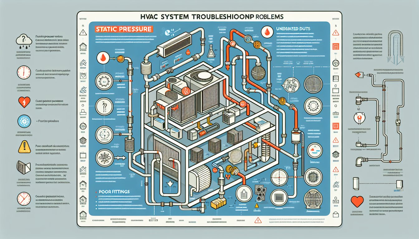
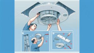
Undersized return grilles are the most common single contributor. Most residential systems need 1 square foot of return grille free area per 400 CFM. A 1,200 CFM system needs at least 3 sq. ft. of return area. Undersized grilles force high face velocities (above 400 FPM), which generate turbulence and add 0.05–0.15 in. w.c. that could be eliminated simply by specifying a larger grille. Injection-molded return grilles with high free-area ratios (≥75%) and fixed blade angles of 35–45° minimize this resistance.
Leaky Duct Connections
Leaky duct connections are the second major category. A gap of 1/16 inch around a duct connector allows air to bypass through wall or ceiling cavities at lower pressure than pushing through the designed airflow path. This bypass changes the pressure distribution across the whole system. The fix is consistent: use injection-molded duct connectors with integral sealing channels that accept foam gaskets, tighten to a controlled torque, and don’t rely on installer-applied mastic that may crack or separate. Our duct connectors include a 3-mm groove that accepts a closed-cell EPDM gasket — tested to maintain seal integrity through 10,000 thermal cycles at -10°C to +70°C.
Sharp Transitions
Sharp transitions are the third culprit. Abrupt duct transitions — square-to-round, large-to-small, or angled takeoffs — create separation zones where airflow detaches from the duct wall and creates turbulence. A 45° angle transition loses 0.03–0.08 in. w.c. per fitting. The equivalent injection-molded gradual transition (15° or less included angle) loses less than 0.01 in. w.c. The geometry difference is small; the static pressure impact is not.
How Do You Reduce Static Pressure Through Better Component Design?
Reducing static pressure starts at the design stage — not during installation, and definitely not by upsizing the blower. The most effective interventions are geometric, material, and assembly-quality improvements in the components themselves.
Pression statique CVC : Causes, Mesures et Corrections avec Composants Plastiques
Long-radius elbows are the single highest-return design change in most systems. Increasing elbow radius ratio from r/D = 0.5 (short-radius) to r/D = 1.5 (long-radius) cuts the K-factor from 0.9 to 0.3. In a system with 6 elbows at 700 FPM, that modification alone reduces static pressure by 0.24 in. w.c. — nearly half the total budget for many residential systems. Injection-molded plastic makes this change practical: the same mold tooling cost applies whether the elbow is short or long radius, and the dimensional accuracy ensures every unit matches the design.
Streamlined Grille Geometry
Streamlined grille geometry is the second high-return modification. Traditional fixed-bar grilles have a free area ratio of 60–65%. High free-area designs with tapered bars and optimized spacing achieve 75–80% free area at the same face dimensions. The pressure drop at 400 CFM drops from 0.08 in. w.c. to 0.04 in. w.c. For a system with 8 supply registers and 4 return grilles, that’s 0.48 in. w.c. in cumulative savings — significant in a 0.8 in. w.c. total budget.
Filter Frame Sizing
Filter frame sizing is often overlooked. A 1-inch filter in a 16×25 frame has a face velocity of 300 FPM at 1,000 CFM — within acceptable limits. A 20×25 frame at the same CFM runs 240 FPM, dropping filter resistance by 35%. This modification doesn’t require duct resizing — just replacing the filter box with a larger injection-molded frame. The installed cost is typically under $150; the static pressure reduction is 0.05–0.10 in. w.c. across the filter’s life as it progressively loads with particulate matter over time.
Combining all three modifications — long-radius elbows, high free-area grilles, and proper filter frame sizing — delivers cumulative static pressure reductions of 0.3–0.6 in. w.c. in most residential systems. This brings previously over-pressured systems well within manufacturer-rated TESP, extending blower motor life from the typical 8–10 years at 1.0+ in. w.c. to the designed 15–20 years at 0.6–0.8 in. w.c. The payback on upgraded plastic components, in energy savings alone, typically runs 2–4 years in systems that run 2,000+ hours annually. When you factor in avoided blower motor replacement costs ($500–$1,500 per unit), the economic case for high-quality components is even stronger.
Long-Term Planning for Static Pressure Compliance
For new construction or major renovation projects, specifying injection-molded plastic components from the start is the most cost-effective approach. The material cost premium over hand-fabricated metal is 10–20% for fittings and connectors; the installed cost difference is negligible when labor is factored in. The difference in long-term static pressure performance, energy use, and component service life more than justifies the specification. Our recommendation at HVACore: build static pressure compliance into your specification sheets, require measurements at commissioning, and design the duct system to a target TESP of 0.6 in. w.c. — giving 0.2 in. w.c. of operating margin for filter loading, natural thermal aging, and the inevitable field modifications that every real project encounters.
Frequently Asked Questions About Static Pressure in HVAC?
Qu'est-ce que la pression statique en CVC ?
Static pressure in HVAC is the resistance to airflow in the duct system, measured in inches of water column (in. w.c.) or Pascals. It represents the force the blower must overcome to push air from the air handler through the ductwork to each supply register and back through the return grilles. Ideal total external static pressure for residential equipment is 0.5–0.8 in. w.c.; values above 1.0 in. w.c. accelerate blower wear, reduce airflow, and lower system efficiency. Every component in the air path — fittings, filters, grilles, coils — contributes a portion of this total resistance.
Quels sont les problèmes courants causés par une haute pression statique dans les systèmes HVAC ?
High static pressure causes five common problems: reduced airflow to rooms furthest from the air handler, hot and cold spots across the building, blower motor overheating and premature failure (typical lifespan cut from 15 years to 8–10 years), increased energy consumption as the motor draws more current against resistance, and excessive system noise from high-velocity air through restricted duct sections. ASHRAE data shows systems running above 1.0 in. w.c. TESP use 20–35% more energy than correctly-balanced systems. Most of these problems can be eliminated by addressing the three to four highest-resistance components rather than replacing the entire system.
Comment les raccords de gaines en plastique réduisent-ils la pression statique par rapport au métal ?
Injection-molded plastic duct fittings reduce static pressure through two mechanisms: lower surface roughness and tighter dimensional consistency. Plastic surface roughness averages 0.4–0.8 μm Ra, compared to 3–10 μm for galvanized steel and up to 30 μm for flex duct liner — reducing the friction factor by 15–25%. Dimensional accuracy of ±0.1 mm ensures designed turning radii are maintained in every unit, controlling the elbow K-factor. Combined, well-specified plastic fittings in a 2,000 CFM system can reduce total static pressure by 0.15–0.25 in. w.c. compared to field-fabricated metal alternatives — often enough to bring an over-pressure system within specification.
Quels matériaux sont utilisés dans les composants plastiques CVC pour les conduits ?
The most common plastics for HVAC ductwork components are ABS (indoor fittings, grilles, filter frames — handles up to 80°C), polypropylene with 20–30% glass fiber (large transition fittings requiring dimensional stability under thermal cycling), ASA (outdoor components requiring UV resistance — condensers, line set covers), and PC/ABS blends (high-temperature applications near heat exchangers, up to 105°C). Material selection affects both the achievable surface finish and the long-term dimensional stability of the component. The wrong material doesn’t fail immediately — it degrades slowly, opening gaps and increasing static pressure over 3–5 years of operation.
Combien coûte la réparation d'une pression statique élevée dans un système CVC ?
The cost to fix high static pressure varies widely by cause. Replacing undersized return grilles with properly-sized injection-molded alternatives costs $50–$200 per grille. Upgrading short-radius elbows to long-radius molded elbows costs $15–$60 each. Sealing leaky duct connections with proper gasketed connectors costs $20–$80 per connection. A filter box upgrade to a larger frame costs $100–$300 installed. Total cost for a comprehensive static pressure correction in a residential system typically runs $300–$1,500 — compared to a blower motor replacement at $500–$1,500 that doesn’t solve the root cause, or a full duct replacement at $3,000–$8,000 that isn’t necessary in most cases.
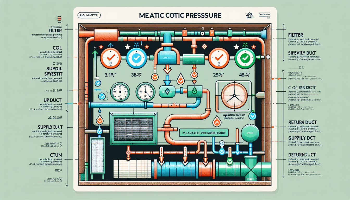
Bottom line: static pressure problems are almost always solvable without replacing the duct system. The highest-impact interventions — long-radius elbows, high free-area grilles, sealed duct connectors, and properly-sized filter frames — address 80% of excess static pressure in most residential and light commercial systems. The key is measuring first, diagnosing the specific high-resistance components, and specifying the right injection-molded parts for the fix.
-
duct fittings: Duct fittings is a term referring to molded or fabricated connectors — including elbows, reducers, tees, and transitions — used to join duct sections and redirect airflow in an HVAC distribution system. ↩
-
airflow resistance: Airflow resistance refers to the cumulative friction and turbulence forces that impede air movement through ductwork, fittings, grilles, and filters, measured as pressure drop across the system. ↩
-
thermoplastic: Thermoplastic is a class of polymer materials that refers to resins softening when heated and solidifying when cooled, making them suitable for injection molding; common HVAC grades include ABS, PP, PC, ASA, and glass-filled nylon. ↩
-
injection molding: Injection molding is a manufacturing process in which molten thermoplastic is injected under pressure into a precision steel mold cavity, then cooled to produce complex, dimensionally accurate parts at high volume. ↩