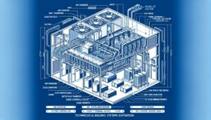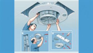

- CAV systems maintain fixed airflow (typically 0.1–2.5 m³/s per zone) regardless of load — only supply temperature changes, not volume.
- Damper blades, CAV box housings, and actuator enclosures are the three plastic-intensive components that determine system reliability over a 15–20 year service life.
- ASA outperforms ABS in UV-exposed CAV installations; glass-filled PA66-GF30 is the standard for structural damper frames under mechanical load.
- At HVACore, we mold CAV housing components to ±0.15mm tolerance — critical for damper blade clearance and actuator mounting accuracy.
A facilities manager at a London hospital told me last year that they had replaced the same section of CAV ductwork three times in eight years. The ducts were fine. The plastic damper actuator housings kept cracking — stress fractures at the mounting bosses, every time. When we looked at the failed parts, the problem was obvious: wrong material, wrong wall thickness, wrong gate location. Someone had specified generic ABS for a component that sees 60°C air, continuous vibration, and 15 years of thermal cycling.
| CAV Basics | Value |
|---|---|
| Airflow control | Fixed volume, variable temperature |
| Typical zone flow | 0.1–2.5 m³/s per terminal unit |
| Primary failure mode | Creep + thermal cycling on plastic parts |
| Target service life | 15–20 years |
CAV systems are simple in concept — fixed airflow, variable temperature. But the plastic components that make them work have to be engineered precisely, or they become the weakest link in a system that is supposed to last two decades. Most installers focus on the controls and the ductwork. The plastic housings and damper frames get specified last, often from a catalogue, and that is where the failures come from.
What Makes a CAV System Different from Other HVAC Configurations?
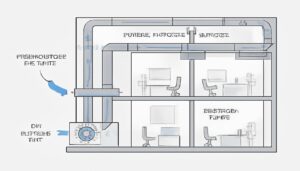
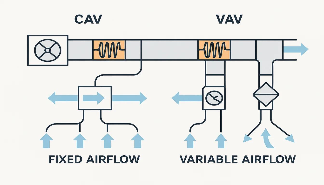
A constant air volume system delivers a fixed airflow rate to each zone at all times, adjusting only the supply air temperature to meet heating or cooling demand. Flow rates are set at commissioning — typically 0.1–2.5 m³/s per terminal unit — and the damper holds that rate constant regardless of system pressure changes or load variation. This is the defining characteristic: the controls change temperature, not volume.
| CAV vs VAV Decision Matrix | Choose CAV | Choose VAV |
|---|---|---|
| Occupancy pattern | Constant (hospital, lab) | Variable (office, retail) |
| Regulation | Minimum ACH mandated | No fixed ACH floor |
| Control complexity | Low preferred | High acceptable |
| Energy priority | Compliance first | Efficiency first |
This simplicity is the engineering point. CAV systems have fewer moving parts than VAV, no pressure-dependent controls, and lower commissioning complexity. For constant-occupancy spaces — hospitals, laboratories, classrooms — where minimum ventilation rates are non-negotiable by regulation, CAV is often the right choice. The tradeoff is energy efficiency: you are always moving full airflow even when the zone does not need it. For a school that runs at full occupancy eight hours a day, that tradeoff is acceptable. For a commercial office with variable occupancy, it is not.
| Parameter | CAV System | VAV System |
|---|---|---|
| Airflow | Fixed (constant) | Variable (0–100%) |
| Temperature control | Supply air temp varies | Airflow volume varies |
| Best for | Tolérance du Noyau CVC | Offices, commercial spaces |
| Control complexity | Low | High |
| Energy at part load | Higher | Lower |
| Plastic component count | Lower | Higher |
| CAV Key Spec | Typical Value |
|---|---|
| Airflow per zone | 0.1–2.5 m³/s |
| Control variable | Supply air temperature |
| Service life target | 15–20 years |
| Primary failure mode | Creep under sustained load + thermal cycling |
Understanding the operating profile of a CAV system matters for material selection. Fixed-position dampers that rarely actuate fail differently from VAV dampers that cycle hundreds of times per day. In CAV, the dominant failure mode is creep under sustained aerodynamic load combined with thermal cycling from seasonal temperature swings. That is why glass-filled nylon outperforms standard ABS in CAV damper frames — not because of impact resistance, but because of creep resistance at elevated temperature over years of continuous static load.
The ventilation regulations that drive CAV adoption are specific about minimum air change rates. Operating theatres in UK hospitals require 20 ACH under HTM 03-01. ISO Class 7 cleanrooms require a minimum of 60 air changes per hour. These are not guidelines — they are enforceable standards. CAV systems deliver the predictability that makes compliance auditable. A VAV system that reduces airflow during low-load periods creates a compliance risk in regulated environments that no facilities manager wants to explain to an inspector.
| Regulation | Minimum ACH | CAV Required? |
|---|---|---|
| HTM 03-01 Operating Theatre | 20 ACH | Yes |
| ISO 14644 Class 7 Cleanroom | 60 ACH | Yes |
| BB101 School Classroom | 5 l/s/person | Typically yes |
| CIBSE Guide A Commercial Office | 10 l/s/person | No (VAV suitable) |
From a plastic component perspective, this regulatory context matters because it sets the service life expectation. A component specified for a hospital CAV system needs to perform to tolerance for 20 years. That requirement eliminates a large portion of the commodity plastic parts catalogue immediately.
Which Plastic Components Are Critical in a CAV System?
| Material | Key Property | CAV Use Case |
|---|---|---|
| PA66-GF30 | Creep resistance 120°C | Damper blades, frames |
| ASA | UV stability 10+ years | Box housings (exposed) |
| PC/ABS blend | Impact + IP54 snap-fit | Actuator enclosures |
| POM | Dimensional stability | Airflow measurement ports |
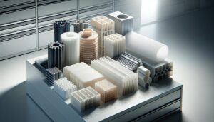
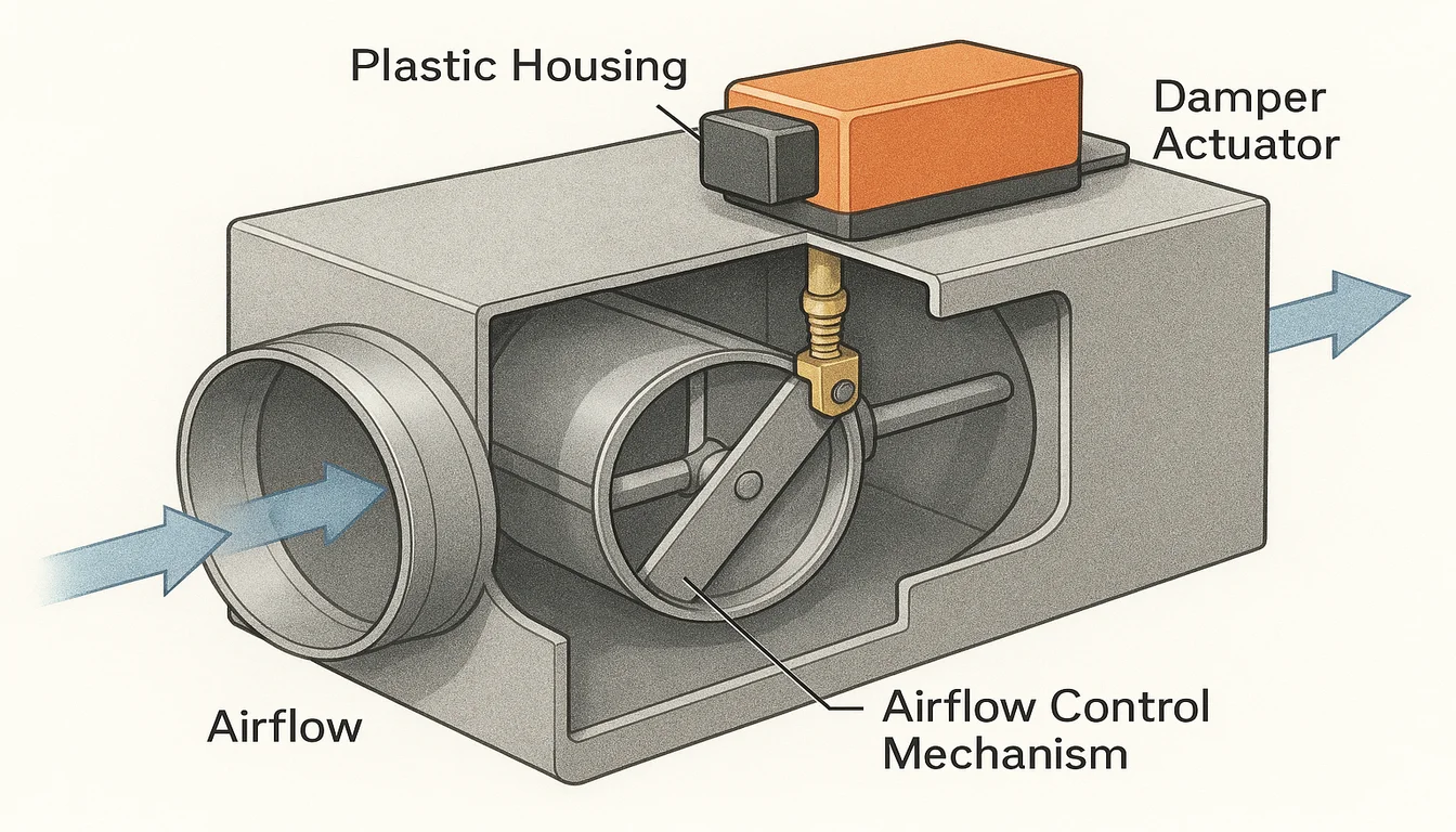
Three component families carry the structural and functional load in CAV terminal units: damper blades and frames, CAV box housings, and actuator enclosures1. Each has distinct material requirements driven by its operating environment — temperature, UV exposure, mechanical load, and service life expectations. Getting any one of them wrong creates a failure mode that propagates through the entire terminal unit.
Damper blades in CAV units run at fixed positions for years without actuation — unlike VAV dampers that cycle constantly. The failure mode is not wear; it is creep under sustained aerodynamic load. At typical supply air velocities of 3–6 m/s, a 400mm x 400mm damper blade carries a sustained aerodynamic pressure of 15–30 Pa. Over 15 years at 120°C continuous service temperature near AHU discharge, an underspecified material will deform enough to break the blade-to-frame seal and throw the zone out of compliance. Glass-filled PA66-GF30 resists creep at 120°C continuous, which is why it is the standard for damper frames in supply air applications.
| Material | UV Stability | Creep at 120°C | Best For |
|---|---|---|---|
| ABS | Poor (yellows 2–3yr) | Poor | Indoor, low-temp |
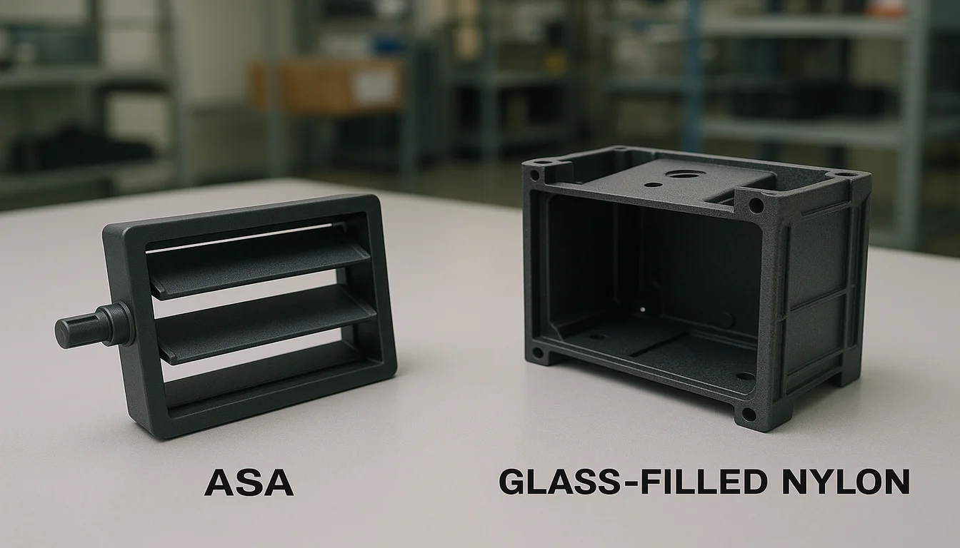
| ASA | Excellent (10yr+) | Moderate | CAV box housings |
| PA66-GF30 | Good | Excellent | Damper frames, brackets |
| PC/ABS blend | Good | Good | Actuator enclosures |
CAV box housings have a different set of requirements. The housing is the structural shell of the terminal unit — it takes the duct connection loads, the actuator mounting loads, and the thermal expansion stresses from heating and cooling cycles. ASA (Acrylonitrile Styrene Acrylate) is the preferred material for exposed or semi-exposed installations because its UV stability is fundamentally better than ABS. ABS yellows and embrittles after two to three years of indirect UV exposure in plant rooms with skylights. ASA holds its properties for 10+ years in the same conditions.
Actuator enclosures must meet IP54 ingress protection as a minimum for HVAC plant room environments — IP65 for installations near condensate lines or cooling coils. The PC/ABS blend is standard here because it combines the impact resistance of PC with the processability of ABS, and it achieves IP54 with standard snap-fit cover designs without gaskets at wall thicknesses of 2.8–3.2mm.
| Component | Material | Key Requirement | HVACore Tolerance |
|---|---|---|---|
| Température de fusion | PA66-GF30 | Creep resistance at 120°C | ±0.15mm |
| CAV box housing | ASA or ABS+UV | UV stability, dimensional accuracy | ±0.20mm |
| Actuator enclosure | PC/ABS blend | Impact resistance, IP54 rating | ±0.15mm |
| Mounting brackets | PA66-GF30 | Vibration fatigue resistance | ±0.10mm |
| Airflow measurement ports | POM | Low friction, dimensional stability | ±0.05mm |
How Does Injection Molding Produce CAV Components to Specification?
CAV box housings require consistent wall thickness — we target 2.5–3.5mm with ±0.3mm variation — to prevent warpage during the thermal cycling that happens every time the AHU cycles on and off. Asymmetric walls are the leading cause of the dimensional drift that makes damper blades bind in their frames after 12–18 months of service. This is a mold design problem, not a material problem — symmetric cooling circuits and consistent gate-to-wall-distance geometry solve it at the tooling stage before the first part is produced.
For injection molding2 CAV damper frames in PA66-GF30, we run at 285–295°C melt temperature with 90°C mold temperature and 50–60 mm/s injection speed. Gate location is always at the geometric center of the longest wall — this pushes the weld line to the low-stress edge zone away from the mounting boss locations where stress concentrations are highest. We have seen bracket failures traced entirely to a gate repositioned 15mm without simulation. The change looked minor on the drawing; the field result was boss cracking at month 14.
| Gate Placement Rule | Effect |
|---|---|
| Center of longest wall | Weld line pushed to low-stress edge |
| Near mounting boss | Weld line at stress concentration → cracking risk |
| Multiple gates | Shorter flow path, lower weld line stress |
| Process Step | PA66-GF30 Damper Frame | ASA Housing |
|---|---|---|
| Melt temp | 285–295°C | 240–260°C |
| Mold temp | 85–95°C | 60–70°C |
| Injection speed | 50–60 mm/s | 60–80 mm/s |
| Post-mold anneal | 80°C × 4h | Not required |
| Gate Position | Weld Line Location | Risk |
|---|---|---|
| Center of longest wall | Low-stress edge zone | Low |
| Near mounting boss | At stress concentration | High — cracking |
| Corner gate | Across load-bearing section | High — fatigue failure |
Post-mold annealing is mandatory for tight-tolerance PA66-GF30 CAV components. We anneal at 80°C for four hours after demolding. This step reduces residual molding stress by 60–70% and prevents the stress-relaxation cracking that shows up at mounting bosses 12–18 months into service. It adds half a day to the production cycle and costs roughly £0.15 per part at our batch sizes. It eliminates a failure mode that costs £800–£2,000 per site visit to diagnose and repair.
Cooling circuit design is the other critical process variable. We run independent cooling circuits on the core and cavity sides of CAV housing tools, with water temperature differential maintained below 5°C between sides. This prevents the differential shrinkage that produces the banana warpage we see in housings produced on tools with shared or inadequately balanced cooling. Mold temperature monitoring is continuous during production — not just at setup — because a blocked baffle on the cavity side is invisible without it.
| Process Parameter | CAV Housing (ASA) | Damper Frame (PA66-GF30) |
|---|---|---|
| Melt temperature | 240–260°C | 285–295°C |
| Mold temperature | 60–70°C | 85–95°C |
| Injection speed | 60–80 mm/s | 50–60 mm/s |
| Patron qui craque | 18–22s | 22–28s |
| Post-mold annealing | Not required | 80°C × 4h for tight-tolerance parts |
What Quality Standards Apply to CAV Plastic Components?
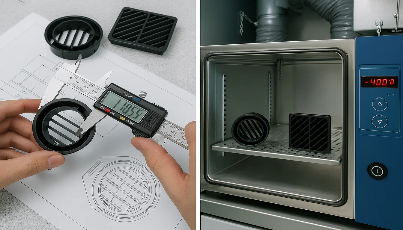
CAV components for commercial and healthcare installations must meet dimensional stability requirements over a 15–20 year service life. At HVACore, we validate CAV housing components against three criteria before production approval: dimensional inspection with CMM to ±0.15mm, thermal cycling test (−20°C to +80°C, 500 cycles), and UV stability testing to ISO 4892-2 for externally-mounted components. These are not optional add-ons — they are the minimum quality gates before any CAV component goes into a regulated installation.
The thermal cycling test is the most revealing. We have seen competitor components pass initial dimensional checks at room temperature, then fail after 100 thermal cycles — the kind of failure that shows up 18 months into a building life when the warranty is still active but the original installer has moved on. The test takes four days. Skipping it to save time is a decision that shows up in service callbacks.
| CAV Installation Type | Required Certification | Documentation Package |
|---|---|---|
| Commercial office | ISO 9001 | Material cert + FAI report |
| Healthcare (HTM 03-01) | ISO 9001 + process records | Mold flow + CMM + material cert |
| Laboratory (ISO 14644) | ISO 9001 + dimensional traceability | Full PPAP package |
| Education | ISO 9001 | Material cert |
For healthcare CAV installations, we supply full mold development3 documentation — mold flow simulation reports, first-article CMM data, material certificates with RoHS and REACH compliance declarations — that satisfies HTM 03-01 ventilation documentation requirements without additional testing burden on the installer. This documentation is prepared during tool validation and delivered with the first production shipment. Most of our healthcare customers use it directly in their as-built building documentation without modification.
| Quality Test | Standard | HVACore Pass Criterion |
|---|---|---|
| Dimensional inspection | ISO 10360 | ±0.15mm on critical dims |
| Thermal cycling | IEC 60068-2-14 | 500 cycles, no warpage >0.3mm |
| UV stability | ISO 4892-2 | ΔE < 3 after 1000h exposure |
| Impact resistance | ISO 180 | Izod > 40 kJ/m² at −10°C |
| CAV Component | Correct Material | Common Mistake |
|---|---|---|
| Damper frame | PA66-GF30 | Generic ABS → creep failure |
| Box housing (UV-exposed) | ASA | Standard ABS → UV embrittlement |
| Actuator enclosure | PC/ABS blend | PP → IP54 snap-fit fails |
| Mounting bracket | PA66-GF30 | ABS → vibration cracking |
Summary?
CAV systems are simple to control but demanding on their plastic components — fixed-position dampers, constant thermal cycling, and 20-year service life expectations leave no margin for underspecified materials or poorly located gates. Getting the material right (PA66-GF30 for structural damper frames, ASA for housings, PC/ABS for actuator enclosures), setting the process parameters correctly, and placing gates to keep weld lines away from stress concentrations eliminates the failure modes that make CAV plastic components a maintenance headache. The components that fail in the field are almost always the ones where one of those three decisions was made by habit rather than by analysis.
Frequently Asked Questions?
| Failure Mode | Root Cause | Prevention |
|---|---|---|
| Boss cracking | CAV CVC Composants en Plastique : Guide des Matériaux et de la Fabrication | Gate center placement + annealing |
| Dimensional drift | Asymmetric cooling | Balanced cooling circuits |
| UV embrittlement | ABS in UV-exposed install | Specify ASA instead |
| Blade seal loss | Creep (wrong material) | PA66-GF30 for damper frames |
What is the difference between CAV and VAV systems in HVAC?
CAV (Constant Air Volume) maintains a fixed airflow rate and varies supply temperature to control zone conditions. VAV (Variable Air Volume) maintains a fixed supply temperature and varies airflow volume. CAV suits spaces with mandatory minimum ventilation (hospitals, labs); VAV suits variable-occupancy spaces where energy savings from reduced airflow are significant.
Which plastic material is best for CAV damper blades?
PA66-GF30 (30% glass-filled nylon) is the standard for CAV damper blades and frames. It resists creep at 120°C continuous service, handles thermal cycling without dimensional drift, and provides the stiffness needed to maintain blade clearance over a 15–20 year service life. ABS and standard PA66 are insufficient for supply-air applications near AHU discharge.
| CAV Plastic Spec Summary | Value |
|---|---|
| Damper blade material | PA66-GF30 |
| Housing material (UV) | ASA |
| Critical tolerance | ±0.15mm |
| Thermal cycling test | 500 cycles, −20°C to +80°C |
What tolerance is required for injection molded CAV box housings?
CAV box housings require ±0.15–0.20mm on damper blade clearance dimensions and actuator mounting features. Tighter tolerances (±0.10mm) apply to airflow measurement port geometry. HVACore validates all CAV housing tooling with CMM first-article inspection before production approval.
How long do plastic CAV components last in service?
Properly specified PA66-GF30 and ASA CAV components have a service life of 15–20 years in standard commercial HVAC applications. The primary failure modes — boss cracking and dimensional drift — are prevented by correct material selection, post-mold annealing, and gate placement that keeps weld lines away from stress concentrations.
| Documentation Type | Included | Standard |
|---|---|---|
| Mold flow simulation | Yes | Before steel cut |
| CMM first-article | Yes | ±0.15mm |
| Material certificate | Yes | RoHS + REACH |
| Thermal cycling data | On request | IEC 60068-2-14 |
Can HVACore supply CAV components with healthcare ventilation documentation?
Yes. We supply mold flow simulation reports, CMM first-article inspection data, material certificates including RoHS and REACH compliance, and process parameter records that satisfy HTM 03-01 and equivalent healthcare ventilation documentation requirements. Lead time for full documentation packages is 5 working days after first-article approval.
-
actuator enclosures are injection-molded plastic housings that protect the electromechanical actuators controlling damper blade position in CAV and VAV terminal units, requiring IP54 or higher ingress protection rating. ↩
-
injection molding is a manufacturing process where molten plastic is injected under pressure into a precision steel mold cavity to produce complex, dimensionally consistent parts at high volume. ↩
-
mold development is the engineering process of designing, building, testing, and validating injection molds before production, including mold flow simulation, trial shots, dimensional verification, and process parameter documentation. ↩