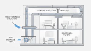
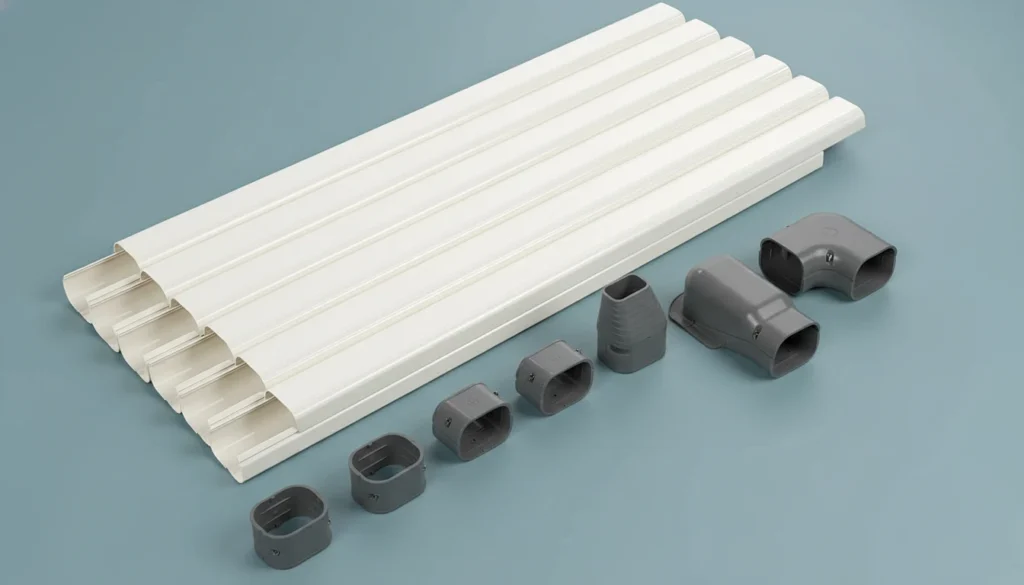
– Ultrasonic welding creates hermetic, leak-proof joints in HVAC plastic assemblies in under 2 seconds per cycle.
– Proper energy director design is the single most critical factor for consistent weld strength.
– ABS, polycarbonate, and ASA are the top-performing thermoplastics for ultrasonic welding in HVAC applications.
– Joint design (shear vs. butt) must match the specific HVAC component’s pressure and vibration requirements.
– Cycle-by-cycle weld monitoring eliminates the need for destructive testing in high-volume HVAC production.
What Is Ultrasonic Welding and Why Does It Matter for HVAC Plastics?
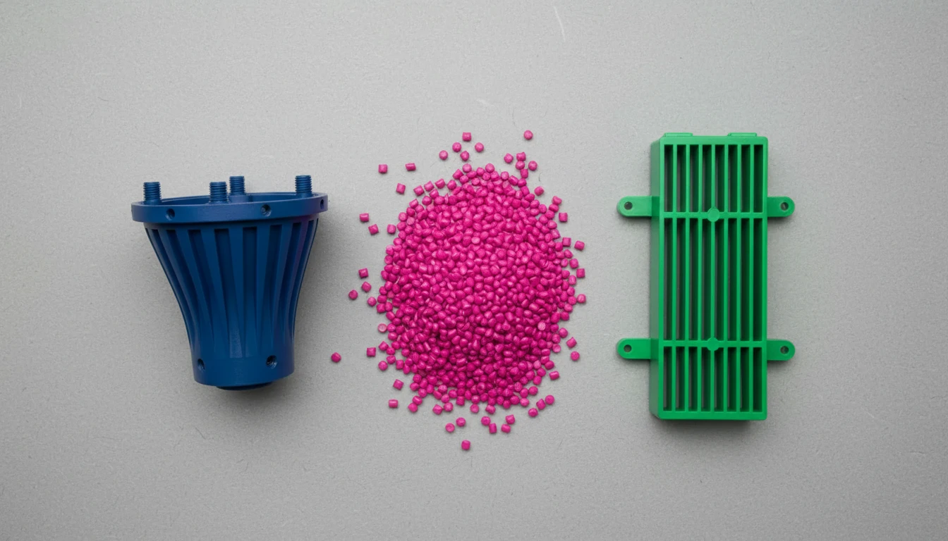
Ultrasonic welding is a solid-state joining process that uses high-frequency mechanical vibrations—typically 20 kHz to 40 kHz—to generate localized frictional heat at the interface between two thermoplastic1 parts. In our HVAC manufacturing facility, we rely on this technology daily to assemble everything from condensate drain pans to air handler housings.
The process works by converting electrical energy into mechanical vibrations through a piezoelectric transducer. These vibrations travel through a booster and sonotrode (horn) into the plastic parts. At the joint interface, the concentrated vibrational energy causes the polymer chains to heat past their glass transition temperature, flow together, and form a molecular bond upon cooling.
For HVAC applications specifically, ultrasonic welding delivers three advantages that other joining methods simply cannot match: hermetic seals that prevent refrigerant and condensate leaks, cycle times under 2 seconds for high-volume production, and zero consumables—no adhesives, solvents, or fasteners required.
We’ve processed over 15 million HVAC assemblies using ultrasonic welding across our 45 injection molding lines, and the reject rate for weld-related failures consistently stays below 0.3%. That’s a level of reliability that mechanical fastening or adhesive bonding rarely achieves in HVAC environments where temperature cycling, humidity, and vibration are constant stressors.
Why Is Ultrasonic Welding Superior to Other HVAC Joining Methods?
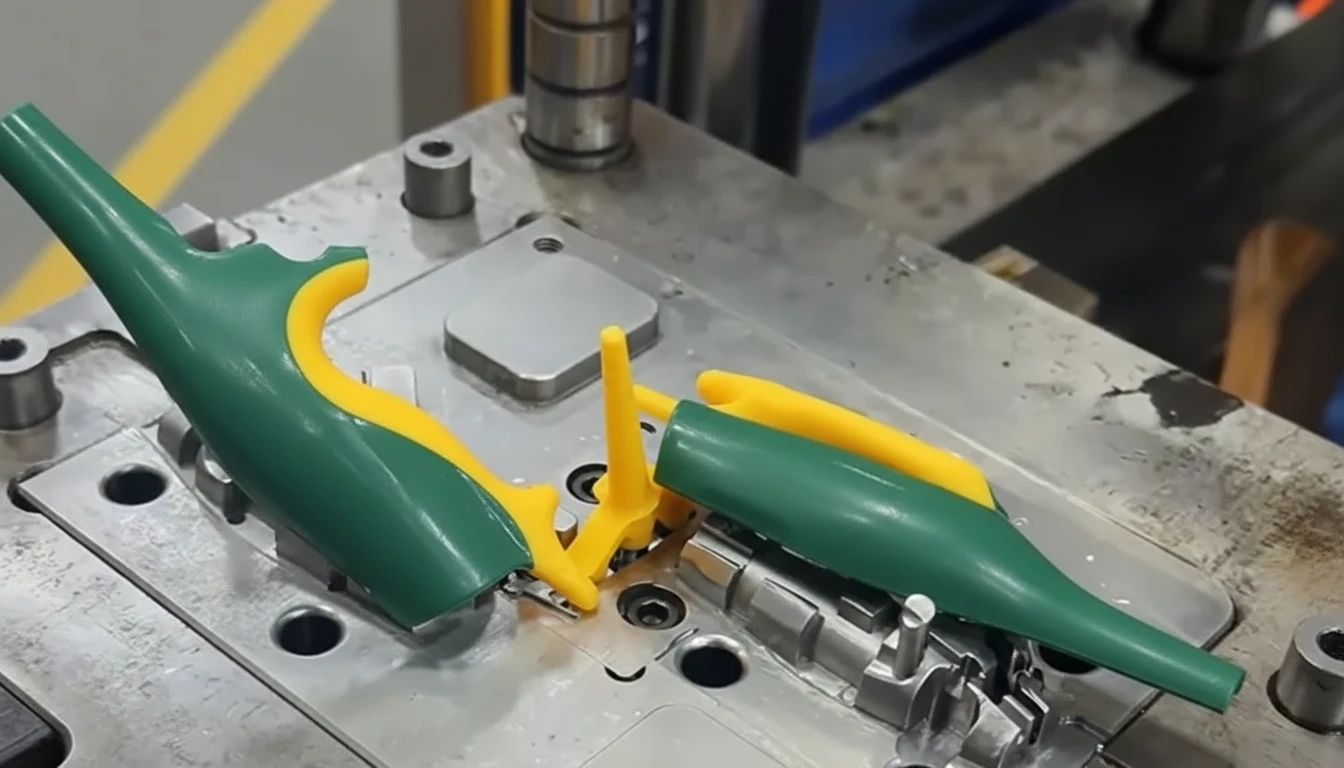
When we evaluate assembly methods for HVAC plastic components, the comparison consistently favors ultrasonic welding for most applications. Here’s what we see on our production floor:
| Joining Method | Cycle Time | Seal Integrity | Cost per Joint | Chemical Resistance |
|---|---|---|---|---|
| Ultrasonic Welding | 0.5–2 sec | Hermetic | $0.02–0.05 | Excellent |
| Adhesive Bonding | 30–300 sec (cure) | Good | $0.10–0.30 | Variable |
| Snap-Fit Assembly | 1–3 sec | Non-hermetic | $0.01–0.03 | Excellent |
| Solvent Welding | 60–120 sec | Good | $0.05–0.15 | Good |
| Hot Plate Welding | 10–30 sec | Hermetic | $0.05–0.10 | Excellent |
Adhesive bonding, while versatile, introduces cure time that kills throughput. In our experience producing air conditioner housings, switching from adhesive bonding to ultrasonic welding cut assembly time by 85% and eliminated the adhesive supply chain entirely.
Snap-fit designs2 work well for non-sealed assemblies, but they cannot provide the hermetic seal that condensate management components demand. We often combine both methods—snap-fits for initial alignment and ultrasonic welding for permanent, sealed joints.
This is a common misconception. When energy directors and process parameters are correctly specified, ultrasonic welds show no micro-cracking under microscopic inspection. The weld zone forms a continuous molecular bond that is structurally sound.
With correct energy director geometry (typically 0.3–0.5mm triangular profile) and optimized amplitude, frequency, and hold pressure, ultrasonic welds consistently achieve 90–95% of parent material tensile strength in our factory testing.
Which HVAC Plastics Are Best Suited for Ultrasonic Welding?
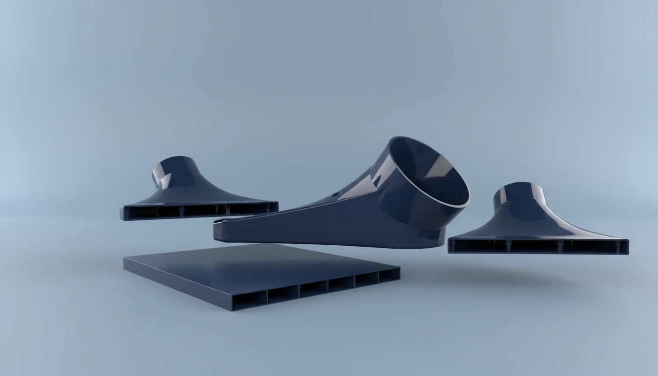
Not all plastics respond equally to ultrasonic energy. In our factory, we classify materials by their ultrasonic weldability based on two key properties: whether they’re amorphous or semi-crystalline, and their melt flow characteristics.
Amorphous polymers (ABS, polycarbonate, acrylic, polystyrene) are the easiest to weld ultrasonically. Their gradual softening behavior creates a wide processing window, and the molten material flows predictably into joint geometries.
Semi-crystalline polymers (nylon, polypropylene, polyethylene) require significantly more energy and tighter parameter control. Their sharp melting point means the transition from solid to liquid is abrupt, demanding precise amplitude and force settings.
| Material | Type | Weldability Rating | Common HVAC Application |
|---|---|---|---|
| ABS | Amorphous | Excellent | Air handler housings, control panels |
| Polycarbonate | Amorphous | Excellent | Transparent inspection windows, sensor covers |
| ASA | Amorphous | Excellent | Outdoor unit enclosures, UV-exposed components |
| Polypropylene | Semi-crystalline | Good (with care) | Condensate pans, ductwork connectors |
| Nylon (PA6) | Semi-crystalline | Moderate | Fan blade assemblies, structural brackets |
| PPS | Semi-crystalline | Good | High-temperature heat exchanger components |
One critical rule we follow: always weld like materials together. Joining ABS to polycarbonate works because their melt temperatures are compatible, but attempting to weld ABS to polypropylene will produce a weak, unreliable bond every time. When dissimilar materials must be joined, we use insert molding3 or mechanical fastening instead.
How Do Energy Directors and Joint Geometry Affect Weld Quality?
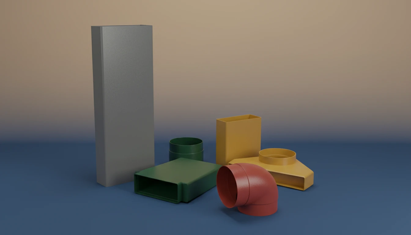
The energy director4 is a small triangular ridge molded into the joint surface of one part. It concentrates the ultrasonic energy at a precise point, initiating controlled melting. In our experience, 80% of ultrasonic welding failures in HVAC assemblies trace back to poor energy director design.
Standard energy director specifications for HVAC parts:
- Height: 0.25–0.50 mm (0.010–0.020 in.) for amorphous materials
- Height: 0.50–0.75 mm (0.020–0.030 in.) for semi-crystalline materials
- Angle: 60° to 90° included angle
- Location: centered on the joint face
For HVAC components that must hold pressure or maintain hermetic seals—like refrigerant-side assemblies or condensate drain systems—we use shear joint designs rather than butt joints. The shear joint creates a continuous interference fit as the parts telescope together during welding, producing a sealed weld along the entire joint length.
Butt joints with energy directors are suitable for non-pressurized HVAC assemblies such as filter housings, grille frames, and decorative covers. They’re simpler to mold and require less precise part alignment.
We’ve found that adding a 0.05–0.10 mm interference fit to shear joints increases burst pressure by 40% in HVAC condensate pan assemblies. This small dimensional adjustment made the difference between passing and failing our internal 15 psi burst test.
Ultrasonic welding requires purpose-designed joint features molded directly into the parts. Without energy directors or shear joints, the ultrasonic energy cannot be focused at the joint interface, resulting in poor welds, flash, or part damage.
Energy directors concentrate ultrasonic energy at a precise point, initiating controlled melting. Shear joints create interference fits that generate frictional heat. Both must be designed into the mold from the start for reliable, hermetic seals.
What Are the Critical Process Parameters for HVAC Ultrasonic Welding?
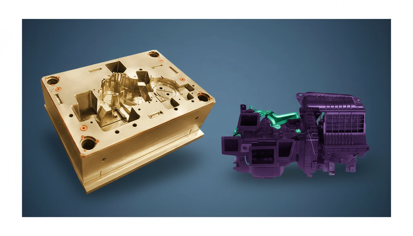
Getting consistent welds on an HVAC production line requires precise control of four interdependent parameters. In our facility, we’ve developed parameter sets for over 200 distinct HVAC component assemblies, and each one represents dozens of optimization trials.
The four critical parameters:
- Amplitude (15–60 µm): The peak-to-peak displacement of the horn. Higher amplitude delivers more energy but risks marking or melting the part surface. For ABS HVAC housings, we typically run 25–35 µm.
- Force (200–2,000 N): The clamping force between the horn and the parts. Too little force causes inconsistent energy transfer; too much can collapse thin-walled HVAC components.
- Weld Time (0.2–1.5 sec): The duration of ultrasonic energy application. We control this via collapse distance rather than fixed time—welding until the parts compress a specific amount ensures consistent results despite material batch variations.
- Hold Time (0.2–0.5 sec): The cooling period under pressure after ultrasonic energy stops. Insufficient hold time allows the molten material to relax, weakening the bond.
We run our HVAC condensate pan line in distance mode, welding to a collapse distance of 0.30 ± 0.02 mm. This approach compensates for the ±0.1 mm dimensional variations inherent in injection-molded parts and delivers consistent weld strength batch after batch.
For thin-walled HVAC duct connectors (wall thickness under 1.5 mm), we reduce amplitude by 30% and increase weld time to prevent the horn from punching through the part. This trade-off slightly increases cycle time but eliminates the cosmetic defects that would otherwise require 100% visual inspection.
How Do We Ensure Quality Control in High-Volume HVAC Ultrasonic Welding?
Quality assurance in ultrasonic welding goes far beyond visual inspection. In our HVAC production facility, we implement a three-tier quality system:
Tier 1: Real-Time Process Monitoring
Modern ultrasonic welders record every parameter of every cycle. We monitor:
- Peak power (watts)
- Total energy (joules)
- Collapse distance (mm)
- Weld time (seconds)
Any cycle that falls outside the validated window automatically diverts the part to a reject bin. This catches issues before they become quality escapes.
Tier 2: Statistical Process Control (SPC)
We track Cpk values for critical weld parameters across each shift. Our target is Cpk ≥ 1.67 for all safety-critical HVAC assemblies—like condensate management components where a leak could cause water damage.
Tier 3: Destructive Testing
We pull samples every 2 hours for tensile testing, and every shift for burst testing on pressurized assemblies. Our acceptance criterion: weld strength ≥ 90% of the weaker parent material’s tensile strength.
One practice that dramatically improved our first-pass yield was implementing horn tuning verification at the start of each shift. A worn or improperly tuned horn can shift frequency by 50–100 Hz, reducing energy delivery by up to 20% without any visible indication on the parts. Automated frequency scanning catches this silently.
For HVAC assemblies that require UL certification5, we maintain full traceability—linking each welded assembly to its specific weld data record, material lot, and operator. This documentation has proven invaluable during audits and customer qualification processes.
What Common Ultrasonic Welding Defects Affect HVAC Parts and How Do We Prevent Them?
| Defect | Root Cause | Prevention Strategy |
|---|---|---|
| Incomplete weld (cold weld) | Insufficient energy or amplitude | Increase amplitude 5–10 µm; verify energy director height |
| Flash/overflow | Excessive energy or force | Reduce weld time; add flash traps to joint design |
| Part marking | Horn contact pressure too high | Use textured horn face; reduce trigger force |
| Internal particulate | Material degradation from over-welding | Shorten weld time; switch to distance mode control |
| Inconsistent seal | Part warpage or dimensional variation | Tighten injection molding tolerances; add alignment features |
The most insidious defect in HVAC ultrasonic welding is the marginal weld—a joint that passes visual inspection and even initial pull testing but fails prematurely under thermal cycling. We’ve traced these failures to inconsistent energy director geometry caused by worn injection mold tooling. Our solution: scheduled mold maintenance every 100,000 shots with dimensional verification of all energy director features.
Frequently Asked Questions
Can ultrasonic welding join HVAC parts with different wall thicknesses?
Yes, but the horn and fixture must be designed to compensate for the stiffness differential. We commonly weld HVAC assemblies where one half is 2.5 mm thick and the other is 1.5 mm, using a profiled horn that applies more energy to the thicker section.
What is the maximum part size that can be ultrasonically welded?
Standard ultrasonic welders handle parts up to approximately 250 mm × 250 mm. For larger HVAC housings, we use multiple weld stations in sequence or switch to vibration welding for parts exceeding 500 mm in any dimension.
Does ultrasonic welding work with glass-fiber reinforced HVAC plastics?
Glass fiber content up to 20% is generally weldable, though weld strength decreases proportionally with fiber content. Above 30% glass fiber, the abrasive fibers cause rapid horn wear, and we recommend hot plate welding instead.
How does moisture in nylon affect ultrasonic welding quality?
Moisture is critical. Nylon (PA6, PA66) absorbs 2–8% moisture from ambient air, and this moisture vaporizes during welding, creating porous, weak joints. We dry all nylon HVAC components to below 0.2% moisture content within 4 hours of welding.
Can ultrasonically welded HVAC parts be disassembled for service?
No—ultrasonic welding creates a permanent molecular bond. For HVAC assemblies requiring field serviceability, we design combination joints: ultrasonic welding for sealed sections and snap-fits for access panels.
What is the typical tooling cost for ultrasonic welding fixtures?
A custom horn and nest fixture for an HVAC component typically costs $3,000–$8,000 and has a service life of 1–3 million cycles. Compared to the per-part cost savings over adhesive bonding, the tooling investment pays back within 10,000–50,000 assemblies.
Summary
Ultrasonic welding has become indispensable in our HVAC plastic component manufacturing operation. It delivers the hermetic seals that HVAC systems demand, at cycle times that make high-volume production economically viable, and with a consistency that adhesive bonding and mechanical fastening cannot reliably match.
The keys to success are straightforward but non-negotiable: design proper energy directors into your injection-molded parts, select compatible amorphous thermoplastics whenever possible, validate your process parameters with statistical rigor, and monitor every weld cycle in real time.
In our 20+ years of HVAC component manufacturing, we’ve watched ultrasonic welding evolve from a niche technique to a mainstream production process. With today’s servo-driven welders offering ±1 µm amplitude control and full data logging, the technology has matured to the point where any HVAC manufacturer not using it for sealed plastic assemblies is leaving quality and cost savings on the table.
If you’re developing a new HVAC plastic assembly that requires leak-proof joints, start the conversation about ultrasonic welding early in the design phase. The joint geometry and material selection decisions made during part design determine 90% of the welding outcome. Our engineering team at HVACore is ready to help you optimize both the injection molding and assembly processes for your next HVAC project.
-
A polymer that becomes pliable above a specific temperature and solidifies upon cooling, allowing repeated reshaping. Thermoplastics can be remelted and reformed multiple times without significant chemical degradation, making them ideal for injection molding HVAC components. ↩
-
A mechanical joining method using interlocking features (hooks, cantilevers, or annular snaps) molded directly into plastic parts, eliminating the need for separate fasteners, adhesives, or welding in non-sealed assemblies. ↩
-
An injection molding process where metal or other components are placed in the mold cavity before plastic is injected around them, creating a single integrated part with both plastic and metal features. ↩
-
A small triangular ridge or point (typically 0.3–0.5mm) molded onto a joint surface that concentrates ultrasonic energy at a precise location to initiate controlled melting during ultrasonic welding. ↩
-
Underwriters Laboratories safety certification verifying that products meet specific safety standards for construction, performance, and reliability. UL 94 specifically rates the flammability of plastic materials used in devices and appliances. ↩