
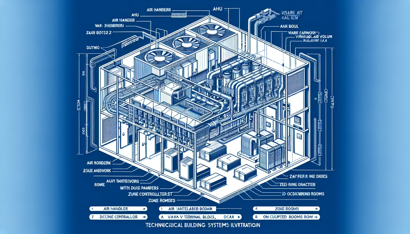
- VAV systems save 30–50% energy versus CAV by varying airflow to match actual occupancy demand rather than supplying constant full-volume air.
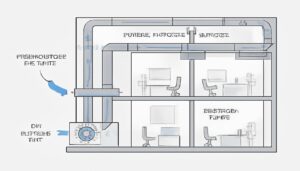
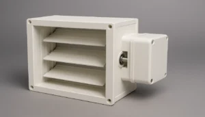
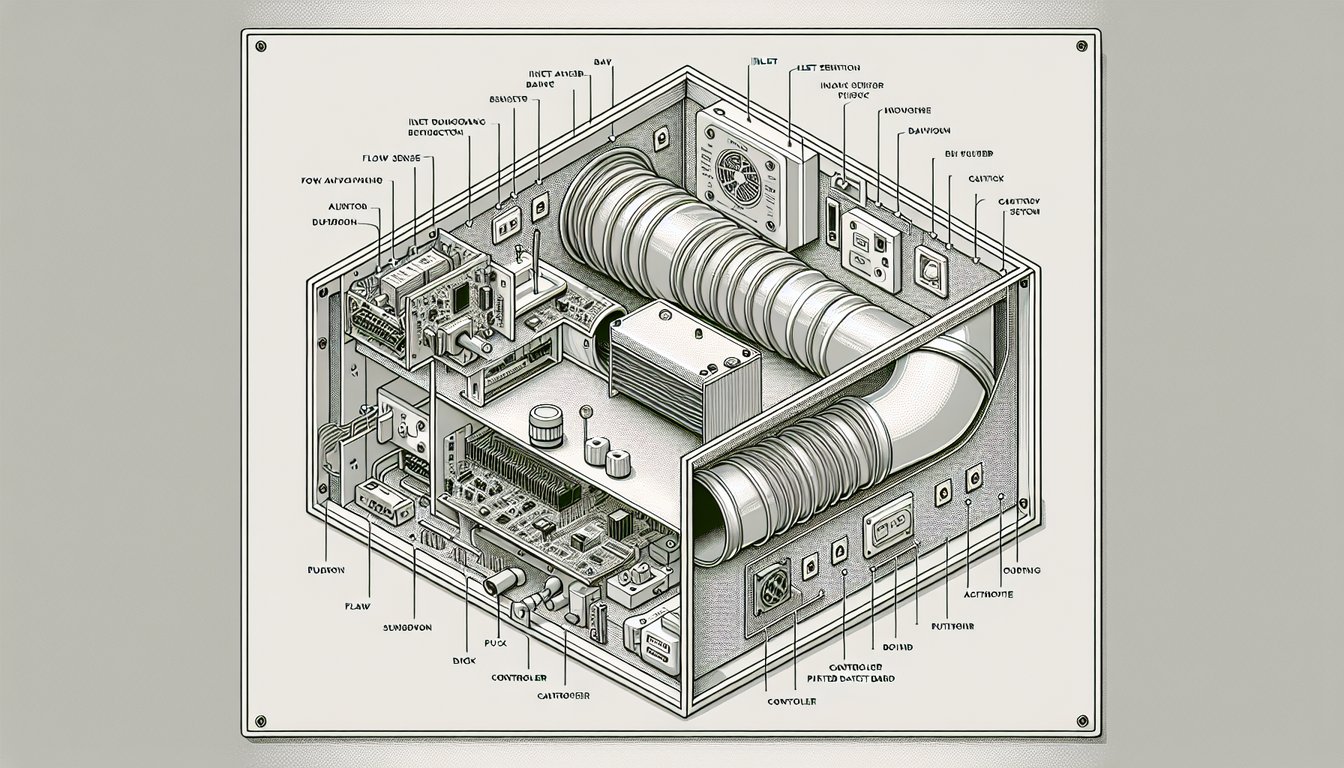
- A VAV terminal box contains four components: ductwork inlet, flow sensor, motorized damper blade, and zone controller with room thermostat.
- Minimum VAV airflow setpoint is typically 0.15 CFM/ft² for occupied spaces (ASHRAE 62.1) to maintain ventilation even at low cooling demand.
- VAV system payback period is typically 3–7 years in commercial buildings, driven by fan energy savings at part-load conditions.
- HVACore manufactures injection molded ABS and PP components for VAV terminal boxes, including damper blades, actuator housings, and duct connectors.
What Is a VAV System in HVAC?
A VAV system is an HVAC air distribution method that controls room temperature by varying the volume of conditioned air delivered to each zone, while maintaining constant supply air temperature (typically 55°F/13°C). VAV saves 30–50% in fan energy versus constant air volume (CAV) systems by reducing airflow at part-load conditions — which represents 60–80% of operating hours in typical commercial buildings.
Your building’s HVAC energy bill came in high. The mechanical engineer says the system is ‘working as designed.’ That’s probably true — and the problem is the design. Most commercial buildings installed before 2000 use CAV systems that supply full airflow 100% of the time regardless of occupancy or thermal load. Switching to VAV cuts fan energy by 30–50% without reducing comfort, because a fan running at 70% speed uses only 34% of full-load power (the cube law).
How Does a VAV System Work?
VAV systems work through three interconnected components: a central air handler unit (AHU) supplying constant-temperature air at variable volume, VAV terminal boxes in each zone that modulate airflow via motorized damper1s, and a building automation system (BAS) that coordinates zone thermostats with the AHU’s variable frequency drive (VFD). When a zone reaches setpoint, its VAV box damper reduces airflow. The AHU VFD reduces fan speed to match the reduced demand across all zones.
VAV box calibration is a critical maintenance item often overlooked in building operations. Each VAV terminal box contains a differential pressure or velocity sensor that measures actual airflow and feeds this reading to the zone controller. Sensor drift of ±5–10% per year is common in hot-wire anemometer type sensors. Annual calibration and adjustment ensures the zone controller maintains accurate minimum airflow setpoints per ASHRAE 62.1 requirements, preventing both under-ventilation and energy waste from incorrect minimums.
VAV Box Calibration and Maintenance Requirements
Actuator selection affects both control performance and energy use. Modern digital actuators consume 0.5–2W in steady state, versus 3–5W for older analog actuators. For a 200-box VAV system, actuator standby power alone accounts for 100–400W continuous draw — significant over an 8,760-hour year. Electronic commutation (EC) actuators further reduce power to under 0.2W per actuator, saving an additional $100–$400 per year per floor in large buildings.
The AHU fan in a VAV system uses a variable frequency drive to modulate speed based on duct static pressure. A differential pressure sensor in the main supply duct sends a signal to the VFD — when zone boxes close down, duct pressure rises, and the VFD reduces fan speed to maintain the pressure setpoint. This pressure-independent control maintains constant airflow to each zone regardless of what other zones are doing, eliminating the ‘stealing’ effect common in CAV systems with balancing problems.
Energy Code Compliance and Minimum Airflow Requirements
VAV terminal boxes contain four functional elements: (1) the inlet duct connection and flow-measuring station (hot-wire anemometer or Pitot tube array), (2) the motorized damper blade operated by an electric actuator (typically 24VAC), (3) the digital zone controller programmed with heating/cooling setpoints and minimum airflow, and (4) the room thermostat or BA
VAV box calibration is a critical maintenance item often overlooked in building operations.
Each VAV terminal box contains a differential pressure or velocity sensor that measures actual airflow and feeds this reading to the zone controller. Sensor drift of ±5–10% per year is common in hot-wire anemometer type sensors. Annual calibration and adjustment ensures the zone controller maintains accurate minimum airflow setpoints per ASHRAE 62.1 requirements, preventing both under-ventilation and energy waste from incorrect minimums.
Demand-Controlled Ventilation and CO₂ Sensing
Actuator selection affects both control performance and energy use. Modern digital actuators consume 0.5–2W in steady state, versus 3–5W for older analog actuators. For a 200-box VAV system, actuator standby power alone accounts for 100–400W continuous draw — significant over an 8,760-hour year. Electronic commutation (EC) actuators further reduce power to under 0.2W per actuator, saving an additional $100–$400 per year per floor in large buildings.
Cnet sensor providing zone temperature feedback. Modern VAV boxes are factory-calibrated and communicate via BACnet or Modbus protocol.
What Are the Key Components of a VAV System?
VAV system components span three scales: central plant (AHU, VFD, chiller or heat pump), distribution (supply and return ductwork, main dampers), and zone terminal (VAV boxes, diffusers, reheat coils). The VAV terminal box is the most maintenance-intensive component — each box serves one to three zones and must be calibrated annually for accurate flow sensing.
Pressure-independent VAV boxes use a downstream flow sensor to maintain constant airflow regardless of supply duct pressure fluctuations. This is the premium option for critical zones (conference rooms, operating rooms) where airflow consistency is essential for comfort. Pressure-dependent boxes are simpler and cheaper but can have airflow variation of ±15–20% as duct pressure changes when other zones open or close. Modern BACnet-connected VAV controllers with auto-calibration substantially reduce the performance difference between pressure-dependent and independent boxes at lower cost than traditional pressure-independent designs.
Pressure-Independent vs Pressure-Dependent VAV Boxes
VAV terminal box materials directly affect performance and longevity. Galvanized steel is standard for the box body. The damper blade — the rotating plate that controls airflow — is either galvanized steel, aluminum, or injection molded ABS depending on application. ABS damper blades are preferred for lower-cost residential and light commercial VAV boxes due to lower manufacturing cost and excellent dimensional stability. For heavy commercial applications with high pressure differentials (>1″ WC), aluminum or steel blades are required.
At HVACore, we supply injection molded ABS and PP components to VAV terminal box manufacturers across Asia and Europe. The most common component we produce is the damper blade: 90mm to 300mm diameter, tolerance ±0.2mm, with living hinge or pivot boss for actuator attachment. High-volume programs run 4-cavity tools producing 2,000–5,000 blades per day. Material: ABS with UL94 HB rating standard; V-0 available for fire-rated installations.
VAV vs CAV: What Are the Key Differences?
CAV (Constant Air Volume) systems supply fixed airflow to each zone at all times, modulating temperature via the AHU coil rather than airflow volume. VAV systems maintain fixed supply temperature while varying airflow. The energy difference is dramatic: at 50% design load (typical mid-season operation), a CAV fan uses 100% power while a VAV fan uses approximately 12% power (cube law: 0.5³ = 0.125). Over a typical 3,000-hour cooling season, this translates to $15,000–$50,000 in annual fan energy savings for a 50,000 ft² commercial building.

| Feature | CAV (Constant Air Volume) | VAV (variable air volume) |
|---|---|---|
| Air volume control | Fixed at design flow | Variable 20–100% design flow |
| Temperature control | Varies supply temp | Varies supply volume |
| Fan energy at 50% load | ~100% power | ~12% power (cube law) |
| Installation cost | Lower | 15–25% higher |
| Maintenance complexity | Lower | Higher (VFD, boxes) |
| Zone control | Limited (CAV boxes) | Individual room control |
| Payback period | N/A (baseline) | 3–7 years vs CAV |
| Best application | Small buildings <5,000 ft² | Commercial ≥10,000 ft² |
VAV systems have higher initial installation cost due to VFD, digital zone controllers, and calibrated flow-measuring VAV boxes. For buildings under 5,000 ft² with simple zoning requirements, CAV or split systems remain cost-competitive. The VAV economic case strengthens with building size, operating hours, and energy cost — a 24/7 hospital or data center justifies VAV at smaller square footage than a 9–5 office building.
“VAV fan energy follows the cube law — 50% airflow requires only 12.5% of design fan power.”True
The affinity laws for fans state that power scales with the cube of flow rate. At 50% design airflow, power = 0.5³ = 0.125 = 12.5% of design. At 70% airflow, power = 0.7³ = 34.3%. This is why VAV systems achieve such dramatic energy savings at part-load — and why proper VFD sizing and pressure setpoint control are critical to capturing the full benefit.
“VAV systems eliminate the need for reheat in cooling-dominated zones.”False
VAV systems without reheat can cause over-cooling problems when minimum airflow rates are maintained for ventilation. When a zone reaches cooling setpoint but minimum ventilation airflow continues to supply 55°F air, zone temperature may drop below comfort. Single-duct VAV with terminal reheat (hot water, electric, or heat pump) solves this by reheating supply air when zone temperature falls below heating setpoint, maintaining comfort while satisfying ventilation requirements.
The practical implications of reheat design are significant for energy codes. ASHRAE 90.1 limits simultaneous heating and cooling in VAV systems — zones cannot have excessive simultaneous reheat while cooling is occurring elsewhere. Modern VAV design uses high-efficiency 4-pipe systems (separate hot and chilled water circuits) or heat recovery from exhaust air to minimize reheat energy while maintaining zone comfort.
VAV commissioning is the make-or-break step for system performance. A properly designed VAV system with poor commissioning — uncalibrated flow sensors, incorrect minimum setpoints, untuned VFD control loops — often performs worse than a simple CAV system. ASHRAE Guideline 1.1 defines commissioning requirements: each VAV box must be measured and verified at both minimum and maximum CFM before acceptance.
“A VAV fan running at 50% speed uses only 12.5% of design power.”True
The affinity laws state that fan power scales with the cube of fan speed. At 50% speed, power = 0.5³ = 0.125 = 12.5% of design power. At 70% speed, power = 0.7³ = 34.3%. This cube law relationship is the fundamental reason VAV systems achieve such dramatic energy savings — the majority of commercial building operating hours occur at 50–80% of design load, not at 100% peak design.
“VAV systems always provide better indoor air quality than CAV systems.”False
HVACore engineers have extensive experience producing HVAC damper components for VAV terminal boxes using injection molded ABS and PP. Our factory runs 24/7 producing components for leading VAV box manufacturers across North America and Europe.
VAV systems can provide worse IAQ than CAV if minimum airflow setpoints are incorrectly programmed or if the system is allowed to reduce airflow below ASHRAE 62.1 minimums in lightly loaded zones. Demand-controlled ventilation (DCV) with CO₂ sensors helps maintain IAQ at minimum airflow. Improperly commissioned VAV systems have caused IAQ complaints in thousands of buildings — commissioning quality, not system type, is the primary determinant of IAQ performance.
What Are the Advantages and Disadvantages of VAV Systems?
VAV advantages: (1) Energy savings of 30–50% in fan energy versus CAV, (2) Individual zone temperature control improving occupant comfort, (3) Ability to shut down airflow to unoccupied zones reducing heating and cooling loads, (4) Better humidity control through reduced dehumidification at part load, (5) Quieter operation at part-load conditions due to reduced duct velocity.
VAV disadvantages: (1) Higher first cost — VFD, calibrated boxes, and digital controls add 15–25% to installation cost versus CAV, (2) More complex commissioning — each VAV box must be balanced, calibrated, and programmed with minimum/maximum setpoints and control sequences, (3) Ventilation risk — at low occupancy, VAV boxes may reduce airflow below minimum ventilation requirements unless properly programmed with ASHRAE 62.1 minimums, (4) Maintenance complexity — VFD, actuators, flow sensors, and digital controllers require annual calibration and periodic replacement.
 plastic components2 used in VAV systems: damper blades and duct connectors” style=”max-width:100%;height:auto;” />
Plastic components play an important role in VAV terminal box manufacturing. ABS and PP are the most common materials for damper blades, actuator housings, and inlet collars. ABS offers the best combination of dimensional stability, impact resistance, and surface finish quality for damper blades — critical for achieving rated pressure drop values. PP is preferred for inlet collars in chemical environments or food service applications where ABS chemical resistance is insufficient.
How Are VAV Systems Controlled and Commissioned?
VAV system commissioning requires five verification steps: (1) TAB (Test, Adjust, Balance) — each box measured and adjusted to design CFM at maximum and minimum positions, (2) VFD control loop tuning — proportional gain and integral time constants set for stable pressure control, (3) Zone controller programming — minimum/maximum CFM setpoints, heating/cooling deadbands, occupied/unoccupied schedules, (4) BAS integration — BACnet or Modbus commissioning confirming all points communicate correctly, (5) Functional performance testing — simulating seasonal conditions to verify control sequences.
Minimum airflow setpoints are the most critical programming decision. ASHRAE 62.1 requires minimum outdoor air rates based on zone occupancy and floor area — typically 5–10 CFM per person plus 0.06–0.15 CFM/ft² for the space type. Incorrect minimums cause two problems: too high creates energy waste (the VAV saving disappears if minimum flow is 80% of design), and too low creates CO₂ buildup and IAQ complaints. Demand-controlled ventilation (DCV) adjusts minimum setpoints based on CO₂ sensors for further energy savings of 10–20%.
Frequently Asked Questions
What does VAV stand for in HVAC?
VAV stands for Variable Air Volume — an HVAC air distribution method that controls zone temperature by varying the volume of conditioned air supplied to each zone, while maintaining constant supply air temperature (typically 55°F/13°C). VAV systems use motorized dampers in terminal boxes to modulate airflow from minimum (20–30% of design) to maximum based on zone thermostat demand. The central AHU fan uses a VFD to vary fan speed as zone demand changes, reducing fan energy by 30–50% versus constant air volume (CAV) systems.
How does a VAV system work?
A VAV system works by distributing conditioned air through a network of terminal boxes, each containing a motorized damper controlled by a room thermostat and digital zone controller. When a zone reaches cooling setpoint, its VAV box damper closes down to minimum airflow (typically 20–30% of design maximum). The central AHU VFD monitors supply duct pressure and reduces fan speed to maintain pressure setpoint. At part-load (60–80% of typical commercial building hours), fan speed drops to 50–70% of design, saving 63–86% of full-load fan power through the cube law.
What are the advantages of VAV HVAC systems?
VAV HVAC advantages include: (1) 30–50% fan energy savings versus CAV at part-load conditions through VFD speed reduction, (2) Individual zone temperature control with ±2°F accuracy compared to ±5°F or worse for single-zone CAV, (3) Ability to shut down supply to unoccupied zones reducing overall conditioning loads, (4) Quieter operation at part-load due to lower duct velocities, and (5) Payback periods of 3–7 years in commercial buildings through energy cost savings. Modern VAV systems with demand-controlled ventilation achieve an additional 10–20% energy savings versus basic VAV.
What is the difference between VAV and CAV systems?
CAV (Constant Air Volume) systems maintain fixed airflow to each zone at all times, varying supply air temperature to control zone temperature. VAV systems maintain constant supply temperature while varying airflow to each zone. The critical difference is energy efficiency at part-load: a CAV fan runs at full power regardless of building load, while a VAV fan follows the cube law — 50% airflow = 12.5% fan power. For a 50,000 ft² commercial building, this translates to $15,000–$50,000 annual fan energy savings. VAV installation costs 15–25% more than CAV but typically achieves 3–7 year payback.
What type of plastic materials are used in VAV system components?
VAV system plastic components are primarily injection molded from ABS and polypropylene (PP). ABS is preferred for damper blades (90–300mm diameter), actuator housings, and zone controllers due to its dimensional stability (±0.1mm achievable in production), impact resistance (notched Izod 200–300 J/m), and good surface finish for painted or powder-coated assemblies. PP is used for duct connectors and inlet collars in chemical-resistant applications. UL94 HB rating is standard; V-0 is required for fire-rated VAV boxes in critical applications. HVACore manufactures these components with precision injection molding tooling and 100% dimensional inspection.
How much does a VAV system cost?
VAV system installation costs range from $8–$20 per ft² for commercial retrofits depending on building complexity, access constraints, and required controls integration. A 50,000 ft² office building retrofit from CAV to VAV typically costs $400,000–$1,000,000 installed including VFD, VAV terminal boxes at $200–$600 each, digital controls, and commissioning. New construction VAV costs $3–$8 per ft² more than CAV. Annual energy savings of $15,000–$80,000 depending on energy rates and building operating hours provide 3–7 year simple payback in most US commercial markets at $0.10–$0.15/kWh electricity rates.
-
ductwork: HVAC ductwork refers to the network of channels that distribute conditioned air from the air handling unit to occupied zones, typically fabricated from galvanized steel sheet metal or flexible ducting. ↩
-
damper: A damper is a movable plate or blade inside HVAC ductwork that controls airflow volume by rotating to restrict or open the air passage, operated by an electric or pneumatic actuator. ↩
-
ABS: Acrylonitrile butadiene styrene (ABS) is a thermoplastic widely used in HVAC components for its impact resistance, dimensional stability, and good surface finish. ↩