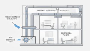
– Geometric Freedom: Injection molding allows for compound curves, variable wall thicknesses, and lofted transitions that are impossible in sheet metal fabrication.
– Turbulence Reduction: Eliminating sharp 90-degree corners and seams significantly lowers static pressure drop, allowing for smaller, quieter motors.
– Integrated Features: Turning vanes, bellmouth entries, and mounting bosses can be molded as a single monolithic unit, reducing assembly labor and leakage points.
– **Simulation Precision:** Computational Fluid Dynamics (CFD) results correlate far better with molded parts due to the high repeatability of the injection process compared to manual metal folding.

Why Does Metal Fabrication Limit HVAC Airflow?
In my years managing HVAC production lines, the biggest constraint on performance has rarely been the fan motor—it has been the duct geometry. Sheet metal fabrication relies on brake presses and folding, which naturally forces designs into boxy shapes with sharp 90-degree angles. From a fluid dynamics in HVAC perspective, every sharp corner creates a recirculation zone—a pocket of "dead air" that effectively narrows the duct and increases resistance.
Complex injection molding removes these constraints. Because plastic enters the mold as a liquid melt—typically materials like Polypropylene (PP) or Acrylonitrile Butadiene Styrene (ABS)—we can design the airspace first and wrap the material around it. We are not bending a sheet; we are defining a flow path. This allows us to maintain constant velocity pressure by smoothly varying the cross-sectional area, something metal fabrication simply cannot do cost-effectively.
Key Parameters: Sheet Metal vs. Injection Molded Geometries
When evaluating HVAC airflow optimization, the manufacturing process dictates the aerodynamic potential.
| Parameter | Sheet Metal Fabrication | Injection Molded Plastic | Airflow Impact |
|---|---|---|---|
| Geometry Constraints | Linear, prismatic, uniform thickness. | 3D compound curves, variable thickness. | Plastic eliminates "hard corners," reducing static pressure drop ($\Delta P$). |
| Surface Consistency | Seams, rivets, raw edges, insulation pins. | Continuous, polished, monolithic. | Smooth plastic surfaces reduce friction losses (lower Reynolds number turbulence). |
| Transitions | Abrupt (Square-to-Round requires welding). | Seamless (Lofted splines). | Prevents flow separation and reduces "air rumble" noise. |
| Internal Structures | Welded vanes (expensive, labor-heavy). | Integrally molded vanes. | Guides air precisely around turns without adding assembly steps. |
How Do We Optimize Designs Using CFD and Molding?
In a recent project for a high-efficiency residential air handler, we utilized CFD analysis for plastics to replace a fabricated metal blower housing. Here is the actual engineering workflow we followed:
1. What Was the Baseline Problem?
The original metal housing had a square exit throat. The CFD simulation showed massive red zones (high pressure/turbulence) at the corners and blue zones (stagnation) in the dead space. The fan was working hard just to push air past the casing’s own geometry.
2. How Did We Apply "Lofting" in Design?
Using 3D CAD, we redesigned the housing using custom ductwork molding principles. We created a "lofted" transition—a mathematical surface that morphs a circle into a rectangle over a curve, rather than a sharp bend.
- Factory Note: Attempting this shape in metal would require five separate stamped parts and welding. In plastic, it is a single cavity cut by a 5-axis CNC mill.
3. Where Did We Place Integrated Turning Vanes?
The air needed to turn 90 degrees immediately after the blower. In the mold design, we added three airfoil-shaped turning vanes directly into the flow path. These split the airstream, preventing it from crashing into the far wall.
- Result: This reduced the pressure drop by 0.15 in. w.g., allowing us to lower the motor RPM and reduce energy consumption.
4. How Did We Handle the "Steel Safe" Adjustments?
We cut the mold "steel safe" (leaving extra metal on the tool, resulting in slightly thinner plastic features). During the T1 trial, we noticed a slight whistle. We removed metal from the mold to round over the leading edge of the vanes. The whistle vanished. This level of micro-adjustment is only possible with a mold.
Counter-intuitively, a perfectly smooth surface can sometimes cause flow separation. In specific high-velocity intake manifolds, a slight texture (SPI C1 or C2) creates a turbulent boundary layer—similar to dimples on a golf ball—that helps the main airflow stick to the curve and reduces drag.
Unlike sheet metal, where manual bending and taping variances lead to inconsistent leakage and flow rates, injection molding produces parts that are micron-perfect clones of the cavity. If the mold design is efficient, 100% of the production run will match that efficiency.
What Are the Advantages and Disadvantages?
| Strategy | Advantages | Disadvantages |
|---|---|---|
| Complex Injection Molding | Efficiency: Drastic reduction in static pressure loss. Space: Ability to snake ducts through tight chassis. Assembly: Snap-fit sealing eliminates tape and mastic. | Cost: High tooling investment ($50k–$200k). Rigidity: Large flat sections require ribbing to prevent drumming/vibration. |
| Metal Fabrication | Flexibility: Zero tooling cost for size changes. Strength: inherently fire-proof and rigid. | Performance: Aerodynamically inefficient. Labor: High assembly and sealing labor costs. |
What Practical Tips Should Mold Designers Follow?
-
Where Should the Parting Line Go?
The flash line (where mold halves meet) creates a small ridge. Never place a parting line perpendicular to high-velocity airflow. It acts as a "trip strip" that generates noise and turbulence. Always design the parting line on the outer flange or in a low-velocity recirculation zone. -
How Do We Prevent Warpage in Vanes?
Internal guide vanes are thick sections of plastic. If you mold them solid, the plastic will shrink and warp the housing. We use coring from the underside or Gas-Assist Injection Molding (GAIM) to hollow out the vanes. This maintains the aerodynamic airfoil shape on the outside while keeping wall thickness uniform. -
Why Is the Bellmouth Critical?
In metal, adding a rounded inlet (bellmouth) requires a separate stamping operation. In plastic, it is just a radius on the tool steel. Always add a generous radius to air intakes. This simple feature smoothes the entry vector of the air, increasing fan efficiency by up to 15% compared to a sharp-edged metal hole.
In Which Scenarios Is This Most Effective?
- Centrifugal Fan Scrolls: The logarithmic spiral (volute) is a complex curve. Molding ensures the expansion angle is mathematically perfect to convert velocity pressure into static pressure.
- Automotive Defrost Ducts: These intricate shapes must fit behind dashboards. Custom ductwork molding allows for thin walls and complex routing that metal cannot achieve.
- Energy Recovery Ventilator (ERV) Cores: The complex manifolds required to separate exhaust and intake air streams can be molded as single pieces, eliminating cross-contamination leakage risks found in metal units.
CFD is a powerful guide, not a guarantee. It cannot fully account for manufacturing realities like flash, ejector pin marks, or subtle warpage. Physical prototyping (using CNC or 3D printing) and wind tunnel testing are mandatory to validate the simulation before cutting the production tool.
Plastics have a higher internal damping coefficient than steel. While sheet metal ducts can vibrate and 'drum' (amplifying fan noise), plastic absorbs vibration energy, resulting in a significantly lower sound power level (dBA) for the unit.
FAQ: Molded Airflow Engineering
Can we injection mold long straight ducts?
Technically yes, but it is rarely cost-effective. Injection molding excels at complex geometries (fittings, elbows, fan housings). For long straight runs, extrusion or traditional sheet metal is preferred. Molding is for the "nodes" of the system, not the lines.
How does shrinkage affect airflow calculations?
If a large fan shroud shrinks unpredictably, the critical gap between the fan blade tip and the housing (tip clearance) changes. If this gap becomes uneven, it ruins efficiency. We use glass-fiber reinforced plastics (like PP-GF20) to minimize shrinkage and maintain circularity.
Is surface roughness a major factor in residential HVAC?
For typical velocities (500–2000 FPM), the difference between a standard mold finish and a mirror finish is negligible regarding pressure drop. However, gross defects like steps, burrs, or gate vestiges are highly detrimental. Focus on smooth geometric transitions rather than surface polish.
Why isn’t plastic used for all commercial rooftop units?
Volume and size. A 20-ton unit might only sell 1,000 units a year. The tooling cost for massive plastic panels is hard to amortize. However, we are seeing more modular plastic "cells" being used for the internal airflow sections to meet strict SEER2 efficiency regulations.
Can we mold insulation directly into the airflow part?
Yes. We use 2-Shot molding or Insert Molding to bond expanded foam (EPS or EPP) directly to the structural plastic. This creates a pre-insulated, condensation-proof airflow channel that performs far better than metal with glued-on fiberglass insulation.

Technical Summary
Improving HVAC system performance with complex injection molding transforms the duct from a passive container into an active airflow component. By leveraging the design freedom of polymers and validating with CFD analysis for plastics, engineers can eliminate the "aerodynamic penalty" of sheet metal—removing sharp corners, integrating turning vanes, and optimizing fluid dynamics in HVAC systems. While the upfront tooling cost is significant, the result is a system that moves more air with less energy, less noise, and zero leakage, offering a decisive competitive advantage in the modern HVAC market.