– Design Freedom: Injection molding allows for compound curves and variable cross-sections that sheet metal fabrication simply cannot achieve.
– CFD Integration: Computational Fluid Dynamics (CFD) is most effective when paired with plastic molding, as the simulation can be perfectly replicated without fabrication variances.
– Turbulence Reduction: Eliminating sharp 90-degree corners and seams reduces static pressure drop, allowing for smaller, quieter fans.
– Surface Consistency: Molded parts provide a repeatable interior surface finish, whereas metal ducts suffer from variances in welding, riveting, and insulation gaps.

What is the "Aerodynamic Penalty" of Metal?
In traditional HVAC manufacturing, we are often limited by the brake press. Bending sheet metal forces us into 90-degree angles, flat surfaces, and sharp transitions. From a fluid dynamics in HVAC perspective, every sharp corner creates a "re-circulation zone" (dead air) and turbulence. This increases resistance (static pressure), meaning we need a bigger, power-hungry motor to push the same amount of air.
Complex injection molding changes the equation. Plastic enters the mold as a liquid, meaning we can design air channels that mimic the organic flow of air itself—smooth, curved, and continuous. We are not bending material; we are shaping the void that the air travels through.
Key Parameters: Sheet Metal vs. Molded Plastic
When we design for HVAC airflow optimization, we compare the constraints of fabrication against the possibilities of molding.
| Feature | Sheet Metal Fabrication | Injection Molded Plastic | Impact on Airflow |
|---|---|---|---|
| Geometry | Linear, prismatic, constant thickness. | 3D Compound curves, variable wall thickness. | Plastic eliminates "dead zones" in corners, maintaining velocity pressure. |
| Transitions | Abrupt (Square-to-Round requires complex welding). | Seamless (Lofted transitions). | Smooth transitions prevent flow separation and noise generation. |
| Internal Surface | seams, rivets, screws, raw edges. | Smooth, continuous, polished. | Plastic reduces friction losses (Reynolds number effects). |
| Guide Vanes | Welded in (expensive, labor intensive). | Molded integrally (free). | Integrated vanes straighten flow, correcting turbulence immediately. |
Step-by-Step: Optimizing Designs with CFD and Molding
In a recent project for a high-efficiency Energy Recovery Ventilator (ERV), we used CFD analysis for plastics to redesign the main airflow manifold. Here is the actual workflow:
1. The Baseline Simulation
We started with the metal prototype. The CFD showed massive red zones (high pressure) at the corners and blue zones (stagnant air) behind the sharp bends. The air wasn’t flowing; it was crashing into the walls.
2. Organic Reshaping ("Lofting")
Using the freedom of molding, we redesigned the duct path. Instead of a box, we created a "swept" geometry. We lofted the entrance (circular) to the exit (rectangular) using a continuous spline curve.
- Factory Note: This shape is impossible to fold out of steel. In a mold, it is just a cavity cut by a 5-axis CNC.
3. Integrating Turning Vanes
The air had to make a hard 90-degree turn. In metal, we would leave it open or weld in a single bent plate. In the plastic design, we molded in a series of three airfoil-shaped turning vanes.
- Result: These vanes split the air stream, guiding it smoothly around the bend without flow separation.
4. The "Steel Safe" Trial
We cut the mold "steel safe" (leaving metal on the mold, making the plastic wall slightly thinner/features smaller). We ran the first shots, tested airflow, and found a slight whistle. We adjusted the leading edge of the vanes in the mold (removing metal) to round them off. The whistle disappeared.
Counter-intuitively, a perfectly smooth surface can sometimes increase drag due to surface adhesion. In specific high-velocity applications, a very fine texture (like a golf ball or shark skin) creates a turbulent boundary layer that allows the bulk air to slide through with less friction.
Unlike sheet metal, where manual assembly variances (misaligned rivets, loose tape) alter airflow, injection molding produces identical parts every cycle within microns. If the mold design is aerodynamically efficient, every single production unit will match that efficiency.
Advantages and Disadvantages of Molded Airflow Components
| Strategy | Advantages | Disadvantages |
|---|---|---|
| Custom Ductwork Molding | Drastic reduction in pressure drop ($\Delta P$). Ability to fit complex ducts into tight chassis spaces. | High tooling cost ($50k+). Only viable for high-volume OEM components, not field-installed ductwork. |
| Metal Fabrication | No tooling cost. Easy to change dimensions for different unit sizes. | Aerodynamically inefficient. Labor-intensive sealing. Prone to air leakage. |
Practical Tips for the Mold Designer
- Watch the Parting Line: The flash line (where two mold halves meet) is an obstruction. Never place a parting line across a critical high-velocity airflow surface. It creates a "trip strip" that generates noise. We always try to hide the parting line on the outer edge or a low-velocity zone.
- Coring for Vanes: When you design internal guide vanes, they often become thick sections of plastic. This leads to sink marks or warping. We must "core out" the vanes from the underside or use gas-assist molding to keep the wall thickness constant while maintaining the aerodynamic shape.
- The Bellmouth Effect: Always mold a radius (bellmouth) into the air inlet. In sheet metal, adding a bellmouth is an extra stamped part. In plastic, it’s just a radius on the mold. This single feature can increase fan efficiency by 10-15%.
HVAC Application Scenarios
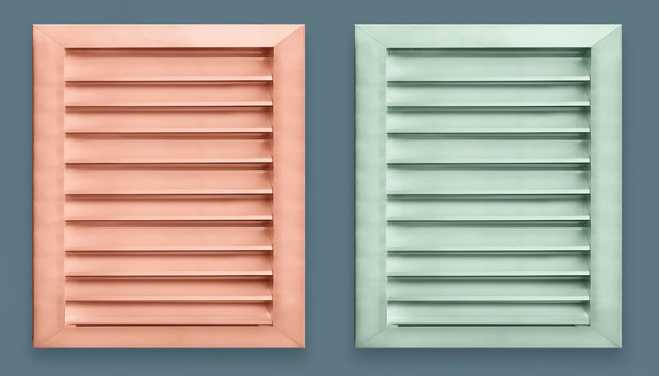
- Centrifugal Fan Scrolls: The "volute" shape is a complex mathematical curve. Injection molding allows us to create the perfect expansion curve to convert velocity pressure into static pressure efficiently.
- Automotive Defrost Ducts: These must snake behind the dashboard. Custom ductwork molding is the only way to navigate these tight spaces while delivering even airflow to the windshield.
- Air Diffusers: Ceiling diffusers rely on the "Coanda Effect" to throw air across a ceiling. Molded plastic lips can be engineered with precise angles to ensure the air sticks to the ceiling, preventing cold drafts on occupants.
CFD is a theoretical guide. It does not account for manufacturing realities like flash, warpage, or ejector pin marks, which can disrupt airflow. Real-world prototype testing (wind tunnel or flow bench) is mandatory to validate the simulation before cutting the final production mold.
Plastic has a higher damping coefficient than steel. While steel ducts can drum or vibrate (acting as a speaker), plastic absorbs vibration energy, resulting in significantly lower radiated noise levels (NC/dBA) from the HVAC unit.
FAQ: Molded Airflow Design
Can we injection mold a long straight duct?
Technically yes, but it is inefficient. Injection molding is best for complex shapes (fittings, manifolds, housings). For long straight runs, extrusion is the correct plastic process, or traditional sheet metal.
How does warpage affect airflow?
Significantly. If a fan shroud warps oval instead of round, the blade tip clearance changes. This causes massive turbulence and noise. We use glass-filled materials and cooling fixtures to ensure the housing remains perfectly circular.
Is a rough surface finish bad for airflow?
For standard HVAC velocities (500–2000 FPM), standard mold finishes (SPI B1 or C1) are negligible regarding friction. Gross geometry defects (burrs, steps, sharp angles) are 100x more detrimental than surface roughness.
Why don’t we see more plastic in commercial rooftop units?
Volume. A 20-ton rooftop unit might sell 500 units a year. The tooling cost for large plastic airflow sections is hard to amortize. However, we are seeing modular plastic designs appearing more often as energy efficiency regulations (SEER2) tighten.
Can we mold the insulation into the plastic?
Yes. We use 2-shot molding or insert molding to bond insulating foam directly to the structural plastic. This prevents the insulation from peeling off and blocking the airflow, a common failure in metal units.
Technical Summary
Improving efficiency with complex injection molding is about leveraging the fluid nature of the polymer to respect the fluid nature of air. By utilizing CFD analysis for plastics, engineers can visualize high-pressure loss zones and eliminate them using geometry that metal fabrication cannot replicate. Whether it is a seamless transition, an integrated turning vane, or a mathematically perfect fan scroll, the result is an HVAC system that moves more air with less energy and less noise. The initial tooling cost is high, but for mass-produced HVAC airflow optimization, the performance gains are unbeatable.