
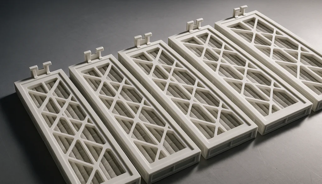
- Dimensional tolerances of ±0.1–0.3 mm in plastic HVAC filter frames directly determine filtration bypass rates and system efficiency.
- PP, ABS, and glass-fiber reinforced nylon each offer distinct advantages in temperature resistance, moisture tolerance, and structural rigidity for filter frame applications.
- The injection molding process—from DFM analysis through mold tooling to post-processing—delivers consistent, high-volume filter frames with wall tolerances as tight as ±0.15 mm.
- Design features such as sealing grooves, snap-fit clips, and standard-dimension compatibility are engineered into the mold, not added as afterthoughts.
- OEM filter frame programs typically require 5,000–50,000 units per run, with lead times of 6–10 weeks from approved drawings to first production shipment.
Why Do HVAC Systems Need Precisely Manufactured Filter Frames?
HVAC systems need precisely manufactured filter frame1s because even 2 mm dimensional gaps reduce filtration efficiency by 15–20%. When a frame holds tolerances within ±0.2 mm across its full perimeter, the compressed gasket seals flush against the housing, eliminating bypass and ensuring that every cubic foot of air passes through the filter media. Precision manufacturing is not optional—it is the foundation of HVAC filtration performance.
| Frame Gap / Deviation | Bypass Rate | System Impact |
|---|---|---|
| ±0.1–0.2 mm | <2% | Meets MERV-13+ sealing requirements |
| ±0.5–1.0 mm | 8–12% | Increased coil contamination & reduced efficiency |
| 2 mm or more | 15–20% | Filtration failure; premature filter replacement |
In our production environment, the most common failure mode we diagnose in returned samples is dimensional deviation caused by inadequate tooling or poor process control. Our engineers confirm that injection molded frames inherently produce repeatable geometry—each part emerges from the same steel cavity with the same critical dimensions. Unlike stamped metal or cut cardboard frames, injection molded plastic frames maintain their shape under the mechanical stress of installation, the thermal cycling of HVAC operation, and the moisture exposure common in air handling units.
“Injection molded plastic filter frames maintain dimensional accuracy within ±0.2 mm across production runs of 50,000+ units.”True
Precision steel tooling combined with process-controlled injection molding2 parameters—melt temperature, injection speed, pack pressure, and cooling time—ensures that each frame produced holds the same critical dimensions. This repeatability is the defining advantage of injection molding over alternative frame manufacturing methods.
“Cardboard and plastic filter frames perform equally well in high-humidity HVAC environments.”False
Cardboard frames absorb moisture and soften over time, losing structural rigidity and compromising the seal against the housing. Plastic frames—particularly those molded in PP or glass-fiber nylon—maintain their geometry and compressive strength even at relative humidity levels of 90% or higher, making them the preferred choice for commercial and industrial HVAC installations.
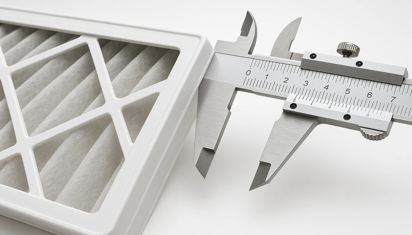
The interface between a filter frame and its housing slot is where filtration success or failure is determined. A frame that is 2 mm undersized creates a gap that turbulent airflow will exploit, carrying particulates directly into the downstream HVAC components3. For hospitals, cleanrooms, and commercial buildings where indoor air quality is a regulatory requirement, this is unacceptable. Injection molded plastic frames, engineered to exact housing specifications, eliminate this risk.
| Frame Material | Typical Tolerance | Moisture Resistance | Service Temperature |
|---|---|---|---|
| Injection Molded PP | ±0.15–0.25 mm | Excellent | Up to 100°C |
| Injection Molded ABS | ±0.15–0.20 mm | Good | Up to 80°C |
| Glass-Fiber Nylon | ±0.10–0.20 mm | Very Good | Up to 130°C |
| Stamped Metal | ±0.3–0.8 mm | Good (coated) | Up to 200°C |
| Cardboard | ±1.0–3.0 mm | Poor | Up to 50°C |
What Materials Are Best for Injection Molded HVAC Filter Frames?
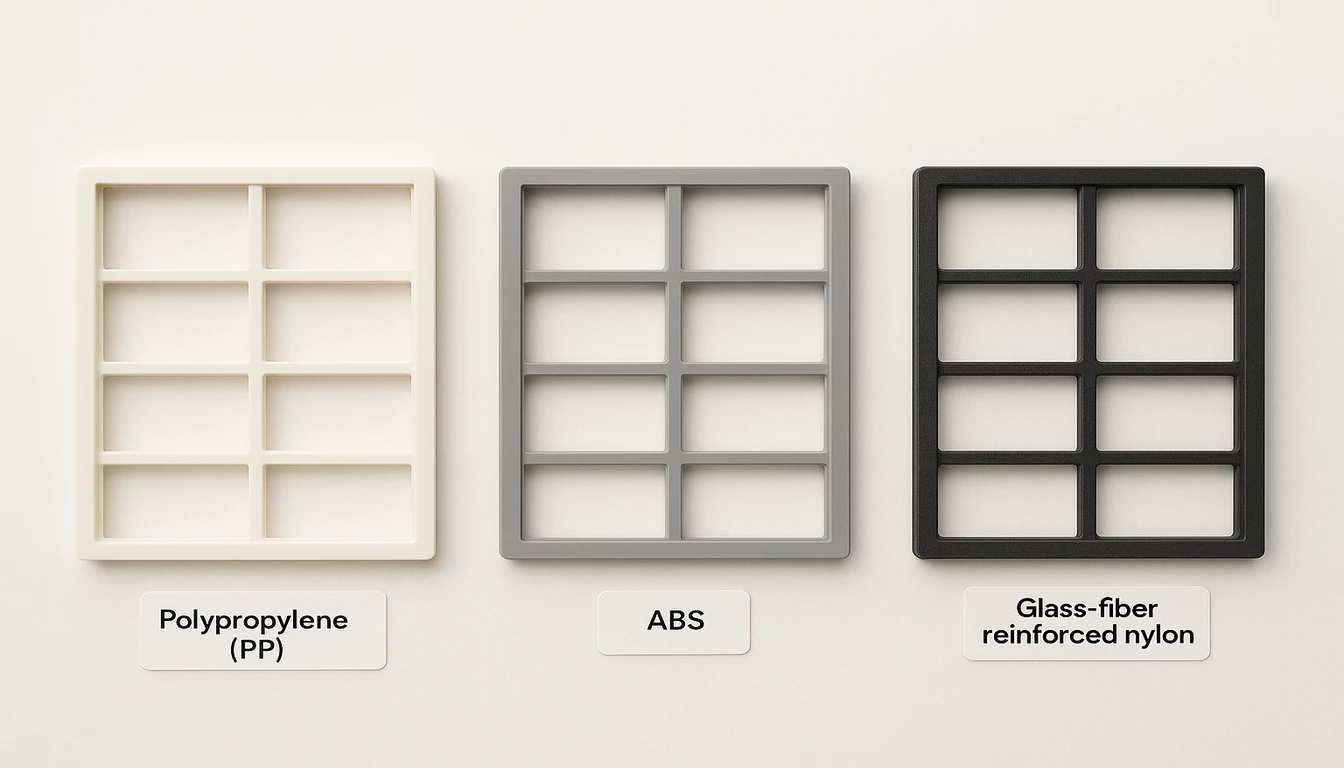
Material selection for plastic HVAC filter frames is one of the most consequential decisions in the design process. The three primary candidates—polypropylene (PP), acrylonitrile butadiene styrene (ABS), and glass-fiber reinforced nylon (GF-PA6 or GF-PA66)—each bring a distinct performance profile that maps to different HVAC application requirements.
Polypropylene (PP) is the workhorse material for residential and light commercial filter frames. It offers excellent chemical resistance, a service temperature up to 100°C, outstanding moisture resistance, and a low material cost. PP’s semi-crystalline structure allows it to spring back under compression, which is critical for maintaining a consistent gasket seal over thousands of installation cycles. For standard residential filters in sizes like 16×20×1 or 20×25×4, PP delivers all required performance at the lowest cost per unit.
| Material | Primary Advantage | Recommended For |
|---|---|---|
| Polypropylene (PP) | Lowest cost, moisture resistant | Residential, light commercial |
| ABS | Best surface aesthetics, stiff | Commercial, visible frames |
| GF-PA66 (30% GF) | Highest strength, heat resistant | Industrial, high-temp HVAC |
ABS provides superior surface aesthetics and dimensional stability compared to PP, making it the preferred choice for visible filter frames in commercial applications where appearance matters. ABS is stiffer than PP and machines to a tighter tolerance, but it is more susceptible to UV degradation and has lower chemical resistance. For indoor, climate-controlled environments, ABS strikes the ideal balance of performance, processability, and cost. In our experience, we recommend ABS specifically when the frame face will be visible through a return grille or when surface texture matching is required.
| Property | PP | ABS | GF-PA66 (30%) |
|---|---|---|---|
| Density (g/cm³) | 0.90–0.91 | 1.03–1.06 | 1.35–1.40 |
| Flexural Modulus (MPa) | 1,200–1,700 | 2,100–2,800 | 6,000–9,000 |
| Max Service Temp (°C) | 100 | 80 | 130 |
| Moisture Absorption (%) | 0.01–0.03 | 0.2–0.4 | 1.5–3.0 (mitigated) |
| Relative Material Cost | Low | Medium | High |
| Best Application | Residential HVAC | Commercial visible frames | Industrial / high-temp |
Glass-fiber reinforced nylon represents the premium tier of HVAC filter frame materials. With 15–30% glass fiber loading, GF-PA66 achieves a flexural modulus of 6,000–9,000 MPa—three to four times stiffer than unfilled PP—and maintains structural integrity at temperatures up to 130°C. This material is specified for industrial HVAC applications involving heat exchangers, rooftop units in high-temperature climates, or clean-process environments where elevated service temperatures and dimensional stability are non-negotiable.
How Are Plastic HVAC Filter Frames Injection Molded?
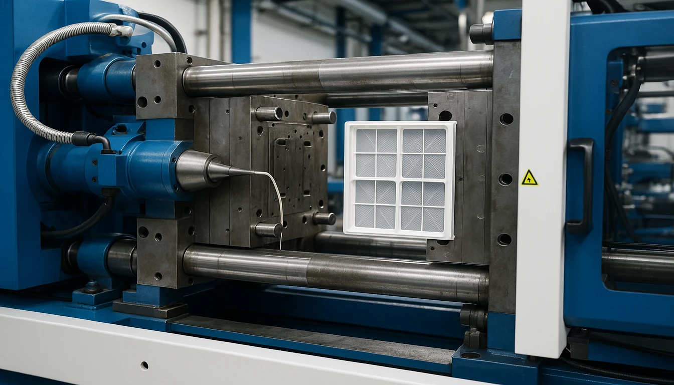
The injection molding process for HVAC filter frames follows a disciplined sequence that begins long before the first pellet of plastic is melted. Design for Manufacturability (DFM) analysis is the critical first step, where the frame geometry is evaluated for wall thickness uniformity, draft angles, gate locations, and ejector pin placement. A well-executed DFM review eliminates the most common defects—sink marks, warping, short shots—before any steel is cut.
Mold tooling is typically machined from P20 or H13 tool steel, with cavities finished to Ra 0.8–1.6 μm for production frames. For high-volume programs exceeding 100,000 annual units, 4-cavity or 8-cavity family molds are standard, reducing per-piece cycle time and tooling cost amortization. Gate design—whether edge gates, submarine gates, or hot-runner systems—is selected based on the frame’s visual and functional requirements, as gate location affects weld line placement and filling balance.
| Cycle Phase | Duration | Key Control Variable |
|---|---|---|
| Injection fill | 2–4 sec | Injection speed & gate size |
| Pack & hold | 4–8 sec | Packing pressure profile |
| Cooling | 10–14 sec | Coolant temp (15–25°C) & wall thickness |
The injection molding cycle for a standard 20×25×1 filter frame in PP typically runs 18–28 seconds, broken down as follows: injection fill (2–4 seconds), pack and hold (4–8 seconds), cooling (10–14 seconds), and mold open/eject/close (2–3 seconds). Cooling time is the dominant variable—it accounts for 50–60% of total cycle time and is controlled by the mold’s cooling channel network, coolant temperature (typically 15–25°C), and the frame’s wall section thickness.
| Phase | Duration | Key Parameters | Quality Impact |
|---|---|---|---|
| Injection Fill | 2–4 seconds | Fill speed, melt temp, gate size | Short shots, jetting risk |
| Pack & Hold | 4–8 seconds | Pack pressure, hold time | Shrinkage, sink marks |
| Cooling | 10–14 seconds | Coolant temp, channel layout | Warpage, dimensions |
| Eject & Reset | 2–3 seconds | Ejector force, mold release | Surface marks, cycle rate |
Post-processing operations for HVAC filter frames are typically minimal by design. Because the molding process produces a finished part geometry, secondary operations are limited to gate trimming (when cold-runner systems are used), dimensional inspection using CMM or optical comparators, and assembly operations such as gasket insertion or label application. For frames requiring UV resistance or color-matching to OEM specifications, in-mold coloring (masterbatch) is used rather than secondary painting.
Process validation is a critical phase that distinguishes production-ready tooling from prototype molds. During Initial Sample Inspection Reports (ISIRs) or First Article Inspection (FAI), engineers measure 30–50 critical dimensions per frame using coordinate measuring machines (CMM) and verify that statistical process capability indices (Cpk) exceed 1.33 for all critical dimensions. This ensures the mold is not only capable of producing good parts—it does so consistently across the full range of process variation. Only after FAI approval does the program transition to full production runs.
“A properly designed 4-cavity injection mold for HVAC filter frames can produce over 500,000 parts before requiring major refurbishment.”True
With proper steel selection (P20 for standard runs, H13 for high-volume), routine maintenance, and process control, HVAC filter frame molds routinely achieve 500,000 to 1,000,000 shot lives. This longevity is critical for OEM programs where consistent part quality is required over multi-year supply agreements.
“Faster injection speeds always produce better-quality HVAC filter frames.”False
Injection speed must be balanced against gate pressure, melt temperature, and cavity filling dynamics. Excessive injection speed can cause jetting, burn marks at the end of flow, and excessive residual stress in the part—all of which compromise dimensional stability and long-term performance. Optimal fill speed is determined through mold flow simulation and validated during First Article Inspection.
What Design Features Define a High-Quality HVAC Filter Frame?
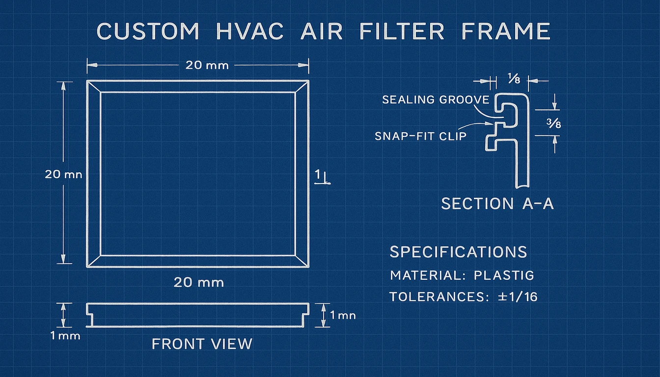
A high-quality HVAC filter frame is defined by four engineered design features: precise wall thickness (2.0–3.5 mm), a continuous sealing groove for gasket compression, positive retention clips to prevent displacement, and dimensional compatibility with ASHRAE 52.2 standard sizes. Each of these features is designed into the injection mold—they cannot be reliably added after the fact.
Wall thickness is the foundational parameter. HVAC filter frames typically use wall sections of 2.0–3.5 mm, selected to balance material usage, structural rigidity, and cooling time. Walls below 1.5 mm risk filling issues and reduced stiffness; walls above 4.0 mm introduce sink marks and extended cycle times. For frames requiring extra stiffness—such as those holding heavy V-bank or rigid cell filters—ribbing is added perpendicular to the primary walls, typically 60–70% of the nominal wall thickness, to increase section modulus without adding material mass.
| Design Feature | Typical Specification | Function |
|---|---|---|
| Wall thickness | 2.0–3.5 mm nominal | Structural rigidity, filling reliability |
| Rib height | 60–70% of wall thickness | Stiffness without sink marks |
| Sealing groove width | 2.0–3.0 mm | Accepts closed-cell foam gasket |
| Gasket compression | 30–50% of free height | Consistent bypass-free seal |
| Snap-fit insertion force | 50–150 N | Positive filter retention under airflow |
| Face dimension tolerance | ±0.5 mm | ASHRAE 52.2 size compatibility |
Sealing geometry is what converts a flat frame into a functional filtration interface. A well-designed HVAC filter frame incorporates a continuous sealing groove or raised bead on the contact face, typically 2.0–3.0 mm wide and 1.0–1.5 mm deep, which accepts a closed-cell foam gasket compressed to 30–50% of its free height when the filter is installed. This controlled compression creates a consistent seal pressure around the full frame perimeter, preventing bypass regardless of minor variation in the housing slot dimensions.
Retention features—snap-fit clips, friction-fit tabs, or integrated latch mechanisms—keep the filter securely seated during operation. In commercial applications where filter changes may occur under airflow conditions, positive retention prevents the filter from being displaced by differential pressure. These features are molded directly into the frame and designed for a defined insertion/retention force cycle—typically 50–150 N insertion force and 20–80 N retention.
Dimensional standards compatibility ensures that OEM and aftermarket filter frames fit existing housing inventories without modification. Standard nominal dimensions (ASHRAE 52.2, MERV-certified sizes) are maintained through precision mold tooling, with critical face dimensions held to ±0.5 mm and filter height (depth) to ±0.3 mm. For OEM programs, actual dimensions are specified on the engineering drawing and validated against customer housing samples before production approval.
How Do Custom Filter Frame Specifications Meet OEM Requirements?
OEM filter frame programs are fundamentally different from standard catalog products. They begin with customer-supplied housing drawings, physical housing samples, or 3D scan data, and they end with a validated injection-molded part that meets the customer’s form, fit, and function requirements—often to tighter tolerances than any commercially available standard size. Our team supports every OEM program through DFM review, mold design sign-off, and First Article Inspection before production launch.
The typical OEM program timeline runs 8–12 weeks from signed drawings to first production shipment. Week 1–2 covers DFM review and engineering alignment; Week 3–6 covers mold design and machining; Week 7–8 covers mold trials and First Article Inspection (FAI); Weeks 9–10 cover customer approval and any mold corrections; Weeks 11–12 cover production launch and initial shipment. Programs requiring complex features—insert molding, overmolding, multi-shot construction—add 2–4 weeks to the tooling phase.
| Parameter | Typical Range | Notes |
|---|---|---|
| Minimum Order Quantity (MOQ) | 5,000–10,000 pcs | Per color/configuration |
| Standard Production Run | 10,000–50,000 pcs | Per order |
| Lead Time (first order) | 8–12 weeks | Includes tooling |
| Lead Time (repeat orders) | 3–4 weeks | From PO to shipment |
| Dimensional Tolerance | ±0.15–0.5 mm | Per drawing specification |
| Tooling Life Expectancy | 500,000–1,000,000 shots | With maintenance |
| Available Finishes | Smooth, textured, custom color | In-mold coloring standard |
Volume requirements for custom OEM programs reflect the economics of injection mold tooling. A single-cavity prototype mold costs $8,000–$15,000; a production 4-cavity tool costs $25,000–$45,000. These tooling costs are amortized across the program volume, making higher volumes essential for competitive per-piece pricing. For programs with annual volumes below 20,000 units, aluminum bridge tooling provides a cost-effective path to production-grade parts while the full program volume is established.
Quality documentation for OEM filter frame programs typically includes First Article Inspection Reports (FAIRs) per AS9102 or customer-specific formats, material certifications, dimensional reports from CMM inspection, and retention samples from each production lot. Many commercial HVAC OEMs require supplier qualification under ISO 9001:2015 or equivalent quality management systems, which governs production process control, inspection frequency, and non-conformance management.
Frequently Asked Questions?
What is the standard wall thickness for an injection molded plastic HVAC filter frame?
Standard wall thickness for injection molded HVAC filter frames ranges from 2.0 to 3.5 mm, depending on the frame size, material, and structural requirements. Smaller residential frames (up to 16×20 inches) typically use 2.0–2.5 mm walls, while larger commercial frames (24×24 inches and above) use 2.5–3.5 mm walls or include structural ribs to maintain rigidity. Walls below 1.5 mm risk filling defects and insufficient stiffness; walls above 4.0 mm introduce sink marks, increase cycle time, and raise material cost per part.
How does polypropylene (PP) compare to ABS for HVAC filter frames?
PP and ABS each suit different HVAC filter frame applications. PP offers superior moisture resistance, chemical resistance, and lower cost—making it the preferred choice for residential and light-commercial filter frames. ABS provides better dimensional stability, surface aesthetics, and impact resistance at room temperature, making it favored for visible commercial-grade frames. In high-humidity or outdoor-exposed applications, PP’s near-zero moisture absorption (0.01–0.03%) gives it a clear advantage over ABS (0.2–0.4%), which can absorb moisture and swell, potentially compromising dimensional accuracy over time.
What causes warping in injection molded HVAC filter frames, and how is it prevented?
Warping in HVAC filter frames most commonly results from non-uniform cooling, unbalanced gating, or material shrinkage differentials across the frame geometry. Semi-crystalline materials like PP and nylon are more prone to warping than amorphous ABS due to anisotropic shrinkage. Prevention strategies include balanced multi-point gating to ensure symmetric filling, optimized cooling channel placement to achieve uniform mold temperature across the frame face, controlled pack pressure to compensate for volumetric shrinkage, and mold flow simulation (Moldflow or equivalent) during the design phase to identify and correct potential warpage before tooling fabrication.
What minimum order quantity (MOQ) is typical for custom OEM plastic filter frames?
Minimum order quantities for custom OEM injection molded filter frames typically start at 5,000 pieces per configuration for standard materials and simple geometries. More complex frames—those requiring insert molding, multi-color construction, or specialized materials like flame-retardant grades—may have MOQs of 10,000–20,000 pieces to justify tooling investment. Some manufacturers offer bridge tooling (aluminum molds) for programs below 5,000 units, allowing production validation before full steel tooling commitment. Annual volume commitments of 50,000+ units typically unlock volume pricing tiers and dedicated tooling investment from the manufacturer.
Can injection molded plastic filter frames meet UL or flame-retardancy requirements?
Yes, injection molded plastic HVAC filter frames can be produced in flame-retardant (FR) grades that meet UL 94 V-0 or V-2 classifications, which are required by many commercial and industrial HVAC specifications. FR-grade PP, ABS, and nylon are compounded with halogen-free or brominated flame-retardant additives and are fully processable through standard injection molding. Material certification to UL 94, along with the Yellow Card listing of the specific resin grade, is typically required for commercial HVAC OEM programs where fire codes apply. Lead times for FR-grade materials may be 2–4 weeks longer than standard grades due to supply chain specifics.
-
filter frame: A filter frame is a structural component that surrounds and holds an HVAC air filter media in place, ensuring a sealed fit within the air-handling unit to prevent bypass airflow. ↩
-
injection molding: Injection molding refers to a manufacturing process in which molten thermoplastic material is injected under high pressure into a precision-machined mold cavity to produce complex, repeatable plastic parts. ↩
-
HVAC components: HVAC components are defined as the individual mechanical and structural parts that together form a heating, ventilation, and air conditioning system, including filters, frames, housings, and ductwork connectors. ↩