
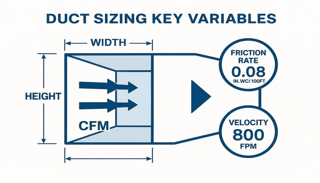
- A duct sizing calculator uses CFM, friction rate, and velocity to determine the correct duct diameter or dimensions for each run.
- ACCA Manual D recommends a friction rate between 0.06 and 0.10 in.wc/100 ft for most residential systems.
- Oversized ducts reduce velocity below 400 FPM, causing poor air distribution and condensation issues.
- Properly sized ductwork from HVACore’s injection-molded components delivers consistent tolerances that match your design calculations.
Why Does Duct Sizing Matter for HVAC Efficiency?
Getting duct sizing wrong is one of the most common causes of uneven temperatures, high energy bills, and premature equipment failure. When ducts are too small, static pressure rises above the system’s capacity, causing the blower to work harder and wear out faster. When ducts are too large, air velocity drops below 400 FPM — the minimum needed to carry moisture out of the airstream — leading to condensation buildup and mold risk inside the ductwork.
From our experience manufacturing injection-molded ductwork components for commercial HVAC contractors, undersized trunk ducts are the most frequent complaint we hear when installers retrofit systems. A duct sizing calculator eliminates the guesswork by giving you exact dimensions based on the actual airflow requirements of each room and run.
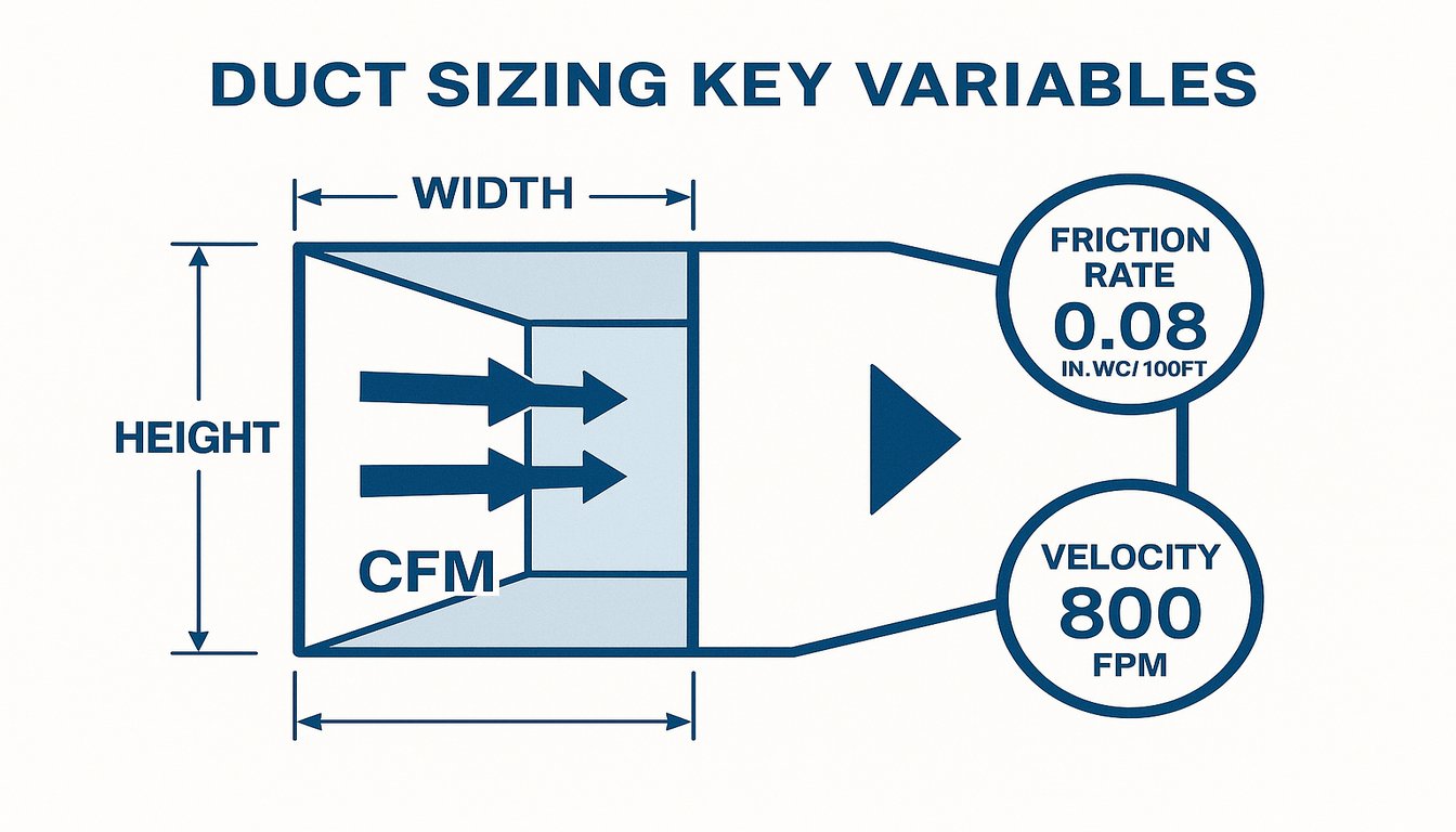
The three primary variables every duct sizing calculator uses are: (1) airflow in CFM1, which tells you how much air each room needs; (2) available static pressure and friction rate2, which tell you how much resistance the system can handle; and (3) maximum velocity, which protects against noise and turbulence. Balance all three, and the system performs quietly and efficiently for decades.
ASHRAE Standard 62.1 establishes minimum ventilation rates by occupancy type, which directly feeds into your CFM requirements. Residential systems typically use ACCA Manual J for load calculations and ACCA Manual D3 for duct design — both feed directly into duct sizing calculators as inputs.
Understanding how these three variables interact is essential for professional HVAC design. CFM alone tells you nothing about pressure or noise. Friction rate alone doesn’t guarantee adequate airflow. Velocity alone won’t fit in your crawlspace. A proper duct sizing calculator weighs all three constraints simultaneously, allowing you to explore trade-offs and optimize for your specific installation environment.
What Are the Key Variables in a Duct Sizing Calculator?
Before you plug numbers into any calculator, you need to understand what each variable means and where it comes from. A duct sizing calculator is only as accurate as the inputs you give it. Using estimated CFM values from rule-of-thumb square footage formulas instead of a proper Manual J load calculation can result in ducts that are 20–30% wrong in either direction.
| Variable | Unit | Typical Range | Source |
|---|---|---|---|
| CFM (airflow) | ft³/min | 50–2,000 per run | ACCA Manual J load calc |
| Friction Rate | in.wc/100 ft | 0.06–0.10 | TEL and available static pressure |
| Velocity (max) | ft/min (FPM) | 400–900 residential; up to 1,500 commercial | System noise and design limits |
| Equivalent Diameter | inches | 4–24 in. (residential) | Calculator output |
| Total Effective Length (TEL) | ft | 100–600 ft typical | Measured from plans |
The friction rate is derived by dividing the available static pressure by the total effective length. Available static pressure is calculated as: Total External Static Pressure (TESP) minus the pressure drops across the air handler, coil, and filter. For a typical residential system with a 0.50 in.wc TESP and 300 ft TEL, the available friction rate works out to roughly 0.10 in.wc/100 ft — a common design target.
Velocity limits exist to control noise. In bedrooms and living areas, keeping velocity below 600 FPM prevents the rushing-air sound that becomes distracting. Supply ducts serving mechanical rooms or utility spaces can safely run at 900–1,200 FPM. Return ducts should stay below 500 FPM to prevent filter bypass and noise transmission back through the grille. Understanding these velocity zones is critical to sizing every section of your ductwork system correctly.
Another key variable is duct material. Galvanized steel, fiberglass-lined ducts, and flexible ducts all have slightly different friction characteristics. A ductulator or calculator that assumes galvanized will give different results if your system uses flex duct or lined ductwork. Always verify the material assumption in your calculator and adjust if needed. Some modern calculators let you select material type directly, which simplifies the design process and reduces field surprises.
How Do You Use a Duct Sizing Calculator Step by Step?
Using a duct sizing calculator correctly requires following a specific sequence. Skipping steps — especially the load calculation — is why so many installs end up with comfort complaints even when the equipment is properly sized. Here is the process we walk our OEM customers through when they are designing duct systems using our injection-molded duct connectors and trunk sections.
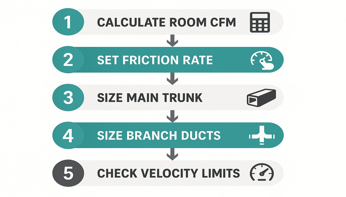
Step 1 is calculating the required CFM for each room or zone. This comes from your Manual J heating and cooling load calculation, not from a rule of thumb. A room with a 1-ton cooling load at a 20°F supply-to-return temperature difference needs (12,000 BTU/h) ÷ (1.08 × 20°F) = 556 CFM. Manual J gives you the BTU/h per room; the equation converts it to CFM. This is the foundation of accurate sizing.
Step 2 is determining your available friction rate. Measure or estimate the total effective length of the longest duct run, including all fittings expressed as equivalent straight lengths. Then: Friction Rate = Available Static Pressure (in.wc) ÷ TEL (per 100 ft). If you have 0.30 in.wc available and a 350 ft TEL, your friction rate is 0.30 ÷ 3.5 = 0.086 in.wc/100 ft.
Step 3 is entering CFM and friction rate into the calculator to get the equivalent round duct diameter. Most calculators also let you enter maximum velocity as a constraint. If the calculator returns a 14-inch round duct but velocity would exceed 700 FPM in a bedroom run, you bump up to 16 inches and re-check the friction loss.
| Round Diameter | Rectangular Equivalent | Area |
|---|---|---|
| 8 in. | 6×10 in. | 50 in² |
| 10 in. | 8×12 in. | 79 in² |
| 12 in. | 9×14 in. | 113 in² |
| 14 in. | 10×16 in. | 154 in² |
| 16 in. | 12×18 in. | 201 in² |
Step 4 is converting round diameter to rectangular equivalent when you need rectangular ducts in tight spaces. The hydraulic diameter formula is: D_eq = 1.3 × (a × b)^0.625 / (a + b)^0.25, where a and b are the rectangular dimensions. A 12-inch round duct is approximately equivalent to a 9×14-inch rectangular duct. Most calculators have a built-in conversion table.
Step 5 is verifying that all branch ducts, not just the main trunk, meet velocity and friction requirements. Size each branch from its own CFM requirement. Then check that the cumulative resistance of the longest run stays within the available static pressure budget. If any branch exceeds velocity limits, upsize it and recalculate.
What Are the Most Common Duct Sizing Mistakes?
After working with hundreds of HVAC contractors who use our custom HVAC components, the same sizing errors come up repeatedly. Most originate from shortcuts taken at the calculation stage rather than at installation. The calculator is only as trustworthy as the process behind it.
The most frequent mistake is using rule-of-thumb CFM values instead of a real load calculation. The often-cited “400 CFM per ton” shortcut ignores climate zone, insulation levels, window area, and occupancy. In a well-insulated modern home, actual cooling CFM can be 30% lower than this rule predicts — leading to oversized ducts with sluggish airflow.
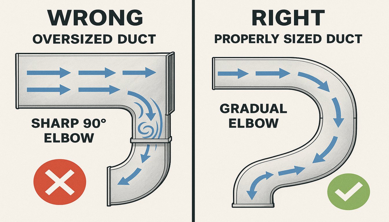
The second most common mistake is ignoring fitting equivalent lengths. A standard 90-degree elbow can add 30–50 equivalent feet of resistance. If your system has six elbows and you ignore them, your actual TEL could be 150–250 ft longer than your measured duct length. This leads to an underestimated friction rate and undersized ducts.
A third mistake is designing all branches at the same diameter as the trunk. The trunk carries cumulative airflow from all branches — it needs to be much larger. Each branch only carries its own room’s CFM. Trunk sizing follows the same calculator logic but inputs the sum of all downstream branch CFMs.
“Velocity below 400 FPM in supply ducts causes moisture problems.”True
When supply air velocity drops below 400 FPM, the air cannot carry entrained moisture vapor efficiently through the duct system. The moisture settles on cold duct surfaces, promoting condensation and mold growth — particularly in humid climates. ACCA Manual D sets 400 FPM as the minimum recommended supply velocity for this reason.
“A larger duct is always safer than a correctly sized one.”False
Oversizing a duct reduces air velocity, which leads to poor air distribution, moisture accumulation inside ducts, and rooms that never reach set temperature. An oversized duct also increases material costs and can create noise when air accelerates through undersized fittings downstream. Correct sizing — not the largest possible size — is always the right approach.
These two sizing mistakes are deeply interconnected: oversized trunks cause low velocity throughout, while undersized branches create local pressure drops that starve individual rooms. Understanding both problems — and how they interact — is what separates experienced HVAC designers from those relying solely on rules of thumb. A good duct sizing calculator surfaces both problems simultaneously by reporting airflow, velocity, and pressure drop for every branch run in the system, making it far easier to diagnose and correct imbalances before installation begins.
“Ductulator tools use the same equations as digital calculators.”True
Both ductulators and digital duct sizing calculators rely on the equal-friction method and ACCA Manual D principles. The difference lies not in the math but in user interface and input flexibility. Digital calculators add velocity constraints, fitting loss tables, and material selection options that slide-rule ductulators omit, making them faster and less prone to reading errors.
“You can use the same friction rate for all duct runs in one system.”False
Friction rate depends on total effective length and available static pressure, which vary by branch. The longest run determines the maximum allowable friction rate. Shorter branches can support higher friction rates because they have less total resistance. Designing all branches with identical friction rate ignores this reality and leads to inconsistent sizing.
ASHRAE Standard 152 defines duct leakage testing procedures using a blower door pressurization test. A well-sealed system should achieve less than 4% total duct leakage as a percentage of system airflow. Injection-molded components with snap-fit socket joints consistently test below this threshold without additional tape or mastic sealant, saving installation time while maintaining system performance.
Leaky ductwork compounds every sizing error. If 20% of conditioned air escapes through duct joints before reaching the registers, the system effectively delivers only 80% of what was designed. Even a perfectly sized duct system fails when the joints are not sealed. This is why injection-molded duct components with precision-fit socket connections reduce field leakage compared to hand-fabricated sheet metal seams.
How Do HVACore Custom Duct Components Affect Sizing Accuracy?
When duct components are manufactured with loose dimensional tolerances, the actual cross-sectional area differs from the nominal size used in the calculator. A nominally 10-inch round duct connection that is actually 9.7 inches in diameter has about 6% less area — enough to push velocity 6% higher than calculated and add measurable friction loss on long runs.

HVACore’s injection molding process holds dimensional tolerances to ±0.3 mm on all critical connection diameters and inner bore dimensions. This means when a contractor sizes a 12-inch round transition using our connectors, the actual installed airflow area matches the design within 0.4%. Duct sizing calculator outputs are no longer estimates — they become reliable predictions.
Our duct sections and elbow components are also engineered with swept-radius bends rather than sharp-cornered fittings. A swept 90-degree elbow has an equivalent length of 20–30 ft, compared to 45–60 ft for a sharp-cornered elbow. When your calculator assumes swept fittings and the installed product delivers them, your total effective length — and therefore your friction rate calculation — stays accurate.
For OEM manufacturers building packaged HVAC units, every internal duct run is a sizing challenge in a constrained space. Our engineering team works directly with OEM design departments to model internal duct paths, verify CFM and velocity targets, and produce injection-molded components that meet those targets in the final assembly. This is where precision molding and duct sizing calculator outputs converge.
Frequently Asked Questions About Duct Sizing Calculators
What CFM per square foot should I use for duct sizing?
There is no single CFM-per-square-foot rule that works reliably across all climates and building types. The often-cited 1 CFM per square foot comes from older, poorly insulated construction in moderate climates. Modern energy-code-compliant homes with good insulation, low-e windows, and efficient air sealing may need only 0.5–0.7 CFM per square foot for cooling. Always use ACCA Manual J to calculate actual room loads in BTU/h, then convert to CFM using the supply temperature difference. Using a flat CFM-per-square-foot assumption can lead to ducts that are 25–40% oversized or undersized compared to the system’s actual needs.
What is the maximum velocity allowed in residential HVAC ducts?
ACCA Manual D recommends keeping supply duct velocity below 700 FPM in occupied living spaces and below 900 FPM in utility areas and mechanical rooms. Return ducts should stay below 500 FPM at the grille face to avoid noise and filter bypass. In practice, most residential designers target 500–600 FPM for supply ducts in bedrooms and common areas. Exceeding 900 FPM in any residential duct creates audible rushing-air noise, increases turbulence losses, and accelerates wear on duct joints and seals. For commercial applications, ASHRAE defines higher allowable velocities depending on occupancy type and system class.
How do I convert round duct size to rectangular duct size?
The standard formula for converting a round duct diameter to an equivalent rectangular duct is the equal-friction method: D_eq = 1.3 × (a × b)^0.625 ÷ (a + b)^0.25, where a and b are the width and height of the rectangular duct in inches. For example, a 12-inch round duct is equivalent to an 8×14-inch or 9×12-inch rectangular duct. Most duct sizing calculators include a built-in conversion table. When using the formula manually, remember that rectangular ducts have higher friction than round ducts of the same cross-sectional area, so equivalent diameters using this formula already account for that difference. Always verify the conversion output against velocity limits for your specific application.
Why does my duct sizing calculator give different results from a ductulator?
A ductulator — the traditional circular slide-rule tool — uses the same underlying equal-friction equations as most online calculators, so significant differences usually trace back to input differences rather than formula differences. Common causes include: different friction rate assumptions (0.08 vs 0.10 in.wc/100 ft changes duct size noticeably), different airflow correction factors for duct material roughness, and whether the tool accounts for altitude correction in locations above 2,500 feet. Digital calculators often add velocity constraints and fitting loss tables that manual ductulators omit. If both tools receive identical inputs — same CFM, same friction rate, same duct material — results should agree within a fraction of an inch on equivalent diameter.
Can I size ductwork using only blower pressure specifications?
Blower pressure alone is not sufficient for duct sizing. You need both the blower’s rated static pressure (typically 0.50 in.wc for residential systems) and the system’s total external static pressure (TESP), which includes filter, coil, dampers, and duct network. After subtracting known losses across the blower, filter, and coil, what remains is available static pressure for the duct runs. This available pressure, divided by total effective length, gives you the friction rate for your calculator. Many sizing errors stem from using blower pressure as a proxy for available duct pressure. Always measure or calculate TESP separately.
-
CFM: CFM, or cubic feet per minute, is a measurement of airflow volume — specifically, how many cubic feet of air pass a given point per minute. ↩
-
friction rate: Friction rate refers to the pressure drop per 100 feet of duct, measured in inches of water column (in.wc/100 ft), used to size duct diameters in HVAC systems. ↩
-
ACCA Manual D: ACCA Manual D is an industry standard published by the Air Conditioning Contractors of America that defines the method for residential and light commercial duct system design. ↩